
Mortars, concrete and concrete products.
In this section you will learn about:
Mortars are used in residential buildings in the following areas as a:
Lime for building purpose is obtained by burning (calcining) carbonate of lime (Limestone). The material is burnt in a kiln for two to three and half days where moisture is driven off leaving rock or quicklime. There are several types of kiln ranging from a simple brick structure to an elaborate rotary type. Lime is used as a component of mortars in brickwork, masonry and plastering, both in render and setting.
This is obtained by crushing rock lime in a machine and then spraying it with the exact amount of water required to take it to a dry powder. This is then conveyed to a separator from which the lime powder is blown off into a storage bin, leaving the impurities behind. It is sold in 25kg paper bags, with 40bags per tonne.
Properties of hydrated lime:
Ready mix mortar manufacturers to produce a plastic or workable mix now use modern additives extensively.
There are two methods used to manufacture Portland cement:
Dry method
Wet method
This is similar to the dry method except that the initial grinding and mixing is done wet. Samples are tested in the laboratory and blending is carried out as required to produce the correct recipe. The mix is then injected into rotary kilns for burning. After burning the method is similar to the dry process.
Approximately 75% of Portland cement produced in Australia is manufactured by the wet process. Approximately one and half tonnes of limestone and one and quarter tonnes of clay or shale are necessary to produce one tonne of cement.
Uses (as a binding agent)
There are several types of Portland cement, which are used as binding agents.
This cement is used in concrete for buildings or civil engineering structures such as dams, bridges, roads, tunnels, airport runways, wharves and jetties. It is also used in precast or prestressed concrete products such as building components, both structural and architectural, bricks, blocks paving slabs and garden ornaments.
This material has special qualities due to extra fine grinding and/or variation in chemical composition by special selection and blending of raw materials. Setting time and ultimate strength are about the same as normal Portland cement. The cost is slightly increased.
This material liberates less heat during early setting and hardening than types GP and HE. It is used therefore in mass concrete to control temperature rises in the concrete. It has somewhat better resistance to some forms of chemical attack than GP or HE because of its chemical composition.
Composition and manufacture of this type of cement are considerably different to Portland cement. It is made from a mixture of limestone and bauxite (bauxite is the principal ore of aluminium). It is hydrated alumina. Aluminous cement can be mixed with Portland cement to accelerate the hydration process and produces a fast rate of strength development.
This material is obtainable in semi-hydrate type, which is made by grinding gypsum (calcium sulphate), calcining, and then regrinding to a fine powder. It is used chiefly for internal decoration and finishes (eg, walls and ceilings). Plaster of Paris has two settings stages – the initial set (plaster) and the final set (hard) during which the material crystallises. This material cannot be used externally because it deteriorates rapidly when exposed to weather.
Pit sand-beach or dune sand
This sand is suitable for use in, mortar or concrete provided it is collected from above the salt water level or washed to remove any salts (eg, Sydney or Botany sands). Pit sand is generally white or cream. Grey sand is of inferior quality because it contains dirt. Bush pit sand, yellow or brown in colour, shrinks because of its 30% or more clay content and is not recommended for use.
River sand
Usually this good quality sand but it is often made up of particles that are smoother and/or coarser than good pit sand.
Crusher fines
This material is produced as a by-product in crushing rock. The particles are rough and splintery in shape (hungry) and therefore require more paste to produce a workable mix than natural sands.
A mixture of coarse and fine particles of sand used for general purpose should pass through a 5mm mesh sieve. All particles passing this size are termed ‘sand’ (and can be used for mortar) while those retained are ‘coarse aggregate’ (and can be used for concrete). Clean sand available for building usually complies with this rule.
Clean sand will not leave a stain on white cloth or on the hands when rubbed together. Salt may sometimes be detected by tasting water after a small quantity of the sand has been immersed in it. A more reliable method is to use clean water to wash some in a small vessel and then add nitrate of silver. Clouding of the solution denotes the presence of salts.
Poor quality sand may be screened or sieved to remove lumps, fine roots and stones. Dust, clay, vegetable matter and salt may removed by washing the sand under running water in a trough or shallow tank.
Crushed sandstone is suitable for mortar when free from dust and clay. Crushed furnace ashes or coke contains corrosive chemicals and is not suitable for use with steel reinforcement. It is, however, good for use in mortar exposed to low furnace heat such as in a domestic coppers, incinerators and barbecues.
Mortar may be defined as a mixture of an aggregate or bulk material and a matrix or binding material. Sand is the aggregate and lime and cement are the binding materials. These materials are combined to form different types of mortar mixtures in accordance with required strength.
Lime mortar is a mixture of slaked rock lime or hydrated lime, clean sharp sand and clean water. This is a comparatively soft type of mortar of low strength. Proportions are one part lime, two and half to four parts sand by volume and sufficient water to bring the mixture to a workable plastic state.
The lime is immersed in water (about 200lt to 50kg bag of lime), usually contained in a large drum or shallow tank, and is well stirred until all the hard lumps have broken up. In this process heat is generated by the decomposing lumps and the liquid appears to ‘boil’. The hot liquid lime is then passed through a sieve, usually 1.5mm mesh, into a heaped ring of sand and when the lime has settled to a soft putty, it is mixed with the sand. The use of rock lime has been discontinued due to its corrosive nature.
Powdered lime may be used directly with measured quantities of sand or it may be soaked for 24 hours in a large drum to ‘fatten’. The lime, sand and water may be mixed by hand on a clean hard surface or may be machine mixed.
This is widely sold by the truck load of 1.25cubic metres or in drums for small jobs. It is generally used for brickwork, when available, because of its convenience and the reduced cost in relation to mixing on site.
Cement mortar is a mixture of Portland cement, clean sharp sand, and clean water and a small proportion of lime. This makes the strongest type of mortar. Proportions are one part cement, 3 to 4 parts sand by volume one-tenth part lime together with sufficient water to make a workable plastic mixture.
Mixing is usually done by hand or by machine on the job. Plastering agents of many kinds, other than lime, are frequently used to make cement mortar more workable. Cement mortar is best when used before the initial set take place, normally about one hour after mixing.
Mortar re-mixed after the initial set loses some strength and should not, therefore, be re-mixed for use.
This medium strength mortar is a mixture or lime, cement, clean sharp and clean water. It sets harder than lime mortar but not as hard as cement mortar. The mixture consists of either one part cement, one part rock or hydrated lime and five and half to six parts sand, or one part cement, two parts rock or hydrated lime and eight to nine parts sand with sufficient water to make a plastic workable mixture. Quantities of materials should be carefully measured and either hand mixed or machine mixed.
Mortars of all types may be coloured red, brown, black, cream or green by adding mineral oxides in dry powder or liquid forms.
Grout, a thin or liquid mortar (usually cement) used for filling up joints. An excess of water makes the mortar weak. Where strength is required, additional cement is added to the grout. It is preferable to wet the work and allow the water to soak in before grouting.
In some areas (such as Sydney) ‘bush’ sand and cement are mixed to produce a bricklaying mortar, in ratio of 1:5. Bush sand contains a clayey loam which produces a very workable mix but which is susceptible to shrinkage. For low-level residential work this does not pose any real problems.
Proprietary admixtures are available for mortars and usually take the form of air in training agents and are used to make the mixture more ‘plastic’ and easier to use. However, caution should be observed with the use of all admixtures as they are often used contrary to the manufactures recommendations and their effects are often misunderstood by the users.
………………………………………………………………………………………………………………………………………………………………………………………………………………………………………
………………………………………………………………………………………………………………………………………………………………………………………………………………………………………
………………………………………………………………………………………………………………………………………………………………………………………………………………………………………
…………………………………………………………………………………………………………………………………………………………
………………………………………………………………………………………………………………………………………………………………………………………………………………………………………
The concept of concrete (probably the world’s most abundant building material) is not a new one. It dates back to Roman times and their use of limestone mortar which was produced by heating limestone and grinding the stone into a powder which, when mixed with water, formed a paste and set both hard and quickly. It was during this era of limestone mortar, that the first concrete was produced when the Romans added sand, crushed stone, brick or broken tiles to the limestone mortar.
However, this concrete was severely limited since the mortar would dissolve on contact with water. So it was a great achievement when a ‘sand’ (really a volcanic ash) was discovered which, when mixed with lime and rubble, hardened and could be used under water as well as in ordinary building. This material was called ‘pozzulan’ since it was produced near the village of Pozzuoli.
This ‘cement’ opened the way to a much greater use of mortars and concrete; however, with the fall of the Roman empire, the use of concrete seems to have declined and not much is recorded about it until the mid eighteenth century. It was not until 1845 that the real prototype of our modern Portland cement was made.
So concrete is hardly a new material, but new aspects of concrete technology are being investigated all the time and indeed the material has been the source of an enormous amount of research for many years.
The ability of plastic concrete to be moulded into any shape probably makes it one of our most versatile building materials and it is difficult to imagine a building project today which does not make use of it in some manner.
Cement Concrete and Aggregates Australia organisation is a great source of information about concrete on their web site www.concrete.net.au/ It provides a number of free publications on topics associated with concrete.
Guide to Concrete for Housing is a free publication from the Cement and Concrete Association of Australia. Either contact the Association by phone on 02 9437 9711, or download it from their web site: www.concrete.net.au
How to find it: On the home page click on the Publications box in the top right, then click on Go attached to lower right side of the box entitled Free in the lower middle of the page – this will bring up many pages of free publications – currently it is item 1 of 111.
Concrete Basics is another good one (and free) and is item 76 in the list mentioned above. It is a 56 page publication that covers all the concrete basics in a concise manner and with a little humour besides.
SAAHB64–2002 Guide to Concrete Construction is a joint production of, and available from, the Cement and Concrete Association of Australia (web site: www.concrete.net.au) and Standards Australia (web site: www.standards.com.au).
Some standards to review include:
AS3972–1997 Portland and Blended Cements
AS1379–1997 Specification and Supply of Concrete
AS3600–2001 Concrete Structures
CSR Products (for Timber, Cement, Plasterboard, Clay & Concrete products) web site: www.csr.com.au/
BORAL (for Timber, Cement, Plasterboard, Clay & Concrete products) web site: www.boral.com.au/
BHP steel reinforcing page provides lots of good information related to steel reinforcing for concrete on the web site: www.onesteel.com/
Concrete is a composite material which consists of a ‘binder’ (Portland cement and water, commonly referred to as the paste) and aggregate. The paste will also usually contain some entrapped air.
Aggregates are generally classified into two groups:
In properly made concrete each particle of aggregate, whether large or small, is completely surrounded by paste, and all spaces between the aggregate particles are completely filled with paste. The aggregates may be considered as inert materials, while the paste (cement and water) is the active cementing medium which binds the aggregate particles into a solid mass.
In a given quantity of concrete, aggregate occupies approximately 75 per cent of the volume while the remaining 25 per cent is taken up by cement paste and air voids. Air voids will remain in even well compacted concretes but usually occupy less than 2 per cent of the total volume unless an air entraining agent has been used.
Fine (sand) |
Coarse (gravel, crushed stone, slag etc) |
Cement and water |
Voids (max 1–2%) |
Aggregate |
Paste |
||
Figure 1: Composition of concrete
The setting or hardening process of concrete takes place through the chemical reaction of the cement and water. This process is called ‘hydration’ and is characterised by the release of heat.
Portland cements are hydraulic cements manufactured from carefully selected raw materials under closely controlled conditions to ensure a high degree of uniformity in their performance.
In Australia, all Portland cements are made to meet the requirements of AS3972–1991 Portland and Blended Cements.
This standard covers five types of Portland cements which can be grouped under the headings general purpose and special purpose.
In general, Portland cement is produced by grinding together Portland cement clinker and calcium sulphate.
Portland cement is generally available in 40 kg bags; that is, 25 bags to the tonne.
General purpose cement is suitable for all uses where special properties are not required. It is used for concrete products and building work where early stripping for forms is not required.
Blended cement consists of a mixture of Portland cement and pozzulands such as fly ash and blast furnace slag.
Blended cements generally have a slower rate of strength gain and less heat of hydration when compared to normal Portland cements; however, with continuous curing, they may achieve higher long–term strength.
Type HE cement is used where high strength is required at an early stage; for example, where it is required to move forms as soon as possible or to put concrete into service as quickly as possible (eg vehicle crossings). It is also used in cold weather construction to reduce the required period of protection against low temperatures.
Type LH cement is intended for use in massive concrete structures such as dams. In such structures the temperature rise resulting from the heat generated during hardening of the concrete is likely to be a critical factor
Type SR cement has better resistance to attack by sulphates in ground water than other types because of its special chemical composition.
White and off–white cements are true Portland cements. White cement is made from selected raw materials and by processes which introduce no colour, staining or darkening to the finished product. Off–white cement is in general use in cottage construction but white cement usually proves cost prohibitive.
High alumina cement is not a Portland cement.
If mixed with Portland cement it can give a rapid or ‘flash’ set. It is characterised by a very high rate of strength development accompanied by a high heat of hydration and by a greater resistance to sulphate and weak acid attack than Portland cements. Curing conditions require very close control for 24 hours after placement.
Cement will retain its quality indefinitely if it does not come in contact with moisture. If it is allowed to absorb appreciable moisture it will set more slowly and its strength will be reduced.
It is therefore important that the storage of bagged cement requires facilities to be as airtight as possible, and the floor should be above ground level to protect against dampness. The bags should be tightly packed to reduce air circulation, but they should not be stacked against outside walls.
If the bags are to be held for a considerable period the stacks should be covered with tarpaulins or water–proof building paper. Doors and windows should be kept closed. Also, a ‘first–in–first–out’ rotation of bags should be maintained at all times.
Setting is the initial stiffening of the cement paste during the period in which the concrete loses its plasticity and before it gains much strength.
This period is affected by the water content of the paste and the temperature. The more water in the paste the slower the set, the higher the temperature the faster the set.
Hardening is the gain in strength which takes place after the paste has set. It is affected by the type of cement used and the temperature. High temperatures cause more rapid hardening.
Water used for mixing good concrete should be free of deleterious amounts of acids, alkalis and oil.
Water containing decayed vegetable matter is particularly to be avoided, as this may seriously interfere with the setting of the cement. Water suitable for drinking will generally be suitable for concrete making.
………………………………………………………………………………………………………………………………………………………..
……………………………………………………………………………………………………………………………………………………………………………………………………………………………………………………………………………………………………………………………………………………………………………………………………………………………………………………………………………………………………………………………………………………………
…………………………………………………………………………………………………………………………………………………………
…………………………………………………………………………………………………………………………………………………………
Aggregates used in concrete should consist of clean, hard, durable particles strong enough to withstand the loads to be imposed upon the concrete.
In general aggregates should consist of either natural sands and gravels (or crushed rocks). Some manufactured aggregates such as blast furnace slag and expanded shale and clays can be equally satisfactory.
Commonly used crushed rocks include:
Unsatisfactory materials include:
Materials such as vermiculite and perlite and other lightweight materials are unsatisfactory as aggregates for structural concrete as they lack strength.
In general, therefore, concrete aggregates should be:
Both coarse and fine aggregates should contain a range of particle sizes. Graded aggregates produce more workable concretes which are less prone to segregation and bleeding.
The particle shape and surface texture of aggregates affect the workability.
For workability, particles should be smooth and rounded. On the other hand, angular materials result in greater strength, so that, in the final analysis, there is little or no difference in effectiveness.
The ultimate decision is one of economics and availability.
The greatest economy is achieved when the largest maximum size aggregate is used.
The factors limiting size are:
If sound and free from excessive quantities of ferrous iron, blast furnace slags are satisfactory concrete aggregates.
Generally they are angular in shape and require a higher percentage of fines to produce workable concrete. Some slags contain quantities of anhydrited lime which, if undetected, can hydrate and cause cracking of the concrete.
Unsound slags can be detected by soaking in water for two weeks, at which time they will show signs of disintegration.
Expanded shale aggregates produce concrete having approximately two–thirds the density of those made with dense aggregates, but with comparable strengths.
Lightweight aggregates may be smooth and rounded or harsh and angular, depending on the method of manufacture.
Since aggregates comprise up to 75% of the volume of concrete, their properties are obviously important. These properties include size and grading as well as cleanliness.
The testing of concrete aggregates is generally carried out to determine:
Good concrete can be made from a wide variety of aggregates provided these are clean and free from harmful impurities.
As the quality of concrete becomes higher, the quality of the aggregate becomes more important and factors such as grading more critical. Good aggregates, although sometimes higher in initial cost, are generally more economical because of the higher quality and lower overall cost of the concrete they produce.
There are several properties of concrete which affect its quality. These are:
Let’s examine these properties in detail.
Compressive strength remains the common criteria of concrete quality and will frequently form the basis of mix design.
For fully compacted concrete made from sound clean aggregates the strength and other desirable properties under given job conditions are governed by the net quantity of mixing water used per bag of cement. This relationship is known as the water/cement ratio, that is, the quantity of water in the mix to the amount of cement present.
Example: A concrete mix having a water/cement ratio of 0.5:1 would require 20 litres (20 kg) of water for each 40 kg bag of cement.
NOTE: 1 litre of water weighs 1 kg.
The ultimate strength of concrete depends almost entirely on the water/cement ratio, for as the ratio increases the strength of the concrete decreases.
This is the measure of the concrete’s ability to resist flexural or bending stresses.
The tensile or flexural strength of concrete is dependent on the nature, shape and surface texture of the aggregate particles to a much greater degree than does the compressive strength.
Concrete may be subject to attack by weathering or chemical action.
In either case the damage is caused largely by the penetration of water or chemical solutions into the concrete and is not confined to action on the surface. The resistance to attack may therefore be increased by improving the watertightness of the concrete.
This is achieved by lowering the water/cement ratio, assuming the concrete is fully compacted.
The workability of concrete, or the effort required to handle and compact it, depends on several factors, as follows:
The cohesiveness of concrete means the ability of plastic concrete to remain uniform, resisting segregation (separation into coarse and fine particles) and bleeding during placing and compaction.
Concrete in the plastic state should be cohesive to prevent ‘harshness’ of the mix during compaction, and to avoid segregation of the coarse and fine components during handling.
Segregation may occur during any of the following events:
Maximum cohesiveness usually occurs in a fairly dry mix. As a rule, the wetter the mix, the more likely it is to segregate. However, segregation can occur in very dry mixes.
Concrete is tested on the site or in the laboratory to determine its strength and durability or to control its quality during construction. These tests help the engineer or job supervisor to determine whether the concrete is as specified and that it is safe to proceed with the job or whether adjustments should be made to the mix.
These tests must be carried out carefully and in the correct manner or the results may be misleading and cause unnecessary delays while they are being checked. Worse still, faulty tests may result in either substandard concrete being accepted or even good concrete being rejected.
There are several ways in which testing can be carried out:
To make a composite sample from the discharge of a mixer or truck, three or more approximately equal portions should be taken from the discharge and then remixed on a non-absorbent board. The sample portions should be taken at equal intervals during the discharge. No samples should be taken at the beginning or the end of the discharge as the concrete at these points may not be truly representative of the whole mix.
When sampling freshly deposited concrete, a number of samples should be taken from different points and recombined to make a composite sample. Care should be exercised to make certain the sample is representative by avoiding places where obvious segregation has occurred or where excessive bleeding is occurring.
The slump test is a measure of the consistency or mobility of concrete and is the simplest way of ensuring that the concrete on the site is not varying.
Slump tests should be done often as an overall control on the various factors that can affect the result. Chief among these factors is the water content of the mix. A variation of the water-cement ratio can result in varying strengths of concrete.
A consistent slump means that the concrete is under control. If the results vary, it means that something else has varied, usually the water, which can then be corrected.
To carry out the slump test, the following equipment is required:
The slump cone is made from sheet metal and is 300 mm high, 200 mm in diameter at the bottom and 100 mm in diameter at the top. It should be fitted with footrests at the bottom and with handles by which it can be lifted.
The tamping rod is 600 mm long, 16 mm in diameter and bullet pointed.
All the equipment must be assembled before your begin testing.
Figure 2 on the next page shows the equipment needed for a slump test and how the measurement is finally taken.
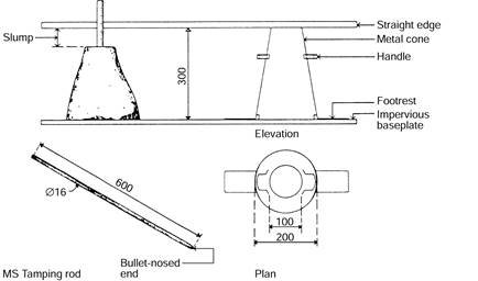
Figure 2: Slump test equipment
To make the test, you should follow these steps. Also refer to Figure 3 on the next page.
1 Moisten the inside of the slump cone and place it large end down on a clean level surface. Hold it firmly in place with a foot on each footrest.
2 Fill the cone, in three approximately equal layers, with concrete from the sample.
Each layer should be tamped down exactly 25 times with the tamping rod, which must be allowed to penetrate each layer.
3 The strokes must be uniformly distributed over the whole surface of the layer and not worked up and down continuously in one place.
4 After the top layer has been compacted, the surface of the concrete is struck off level with the top of the cone and any surplus concrete is removed from around the base.
5 The cone should then be lifted, carefully but firmly, straight up so that the concrete is allowed to subside. Lift the cone smoothly and quickly but do not jerk, twist or take off at an angle lest a false result be obtained.
6 To measure the slump, invert the cone and place it alongside the slumped concrete. Lay the tamping rod on top of the cone and measure the amount of slump, measuring to the highest point of the concrete. The slump is recorded to the nearest 10 mm.
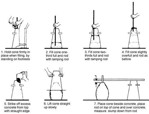
Figure 3: Slump test
In practice, concrete can slump in three ways:
If the concrete collapses or shears away, repeat the test.
The strength of concrete is determined by making specimens, curing them, and then crushing them to ascertain their strength. The preparation of specimens is most important as a badly prepared specimen will nearly always give a low result. Compressive test specimens are normally cylinders 150mm in diameter and 300mm high.
Moulds for the cylinders should be made of metal and be rigid enough to retain their shape during preparation of the specimen. They should be fitted with a base plate which can be fitted securely to the mould to prevent loss of the cement paste.
1 Before filling with concrete, the mould should be clean and coated inside with a very light film of mineral oil.
2 Place the mould on a level surface and fill with concrete from the sample in three equal layers. Rod each layer 25 times with a bullet pointed rod 600mm long and 16 mm in diameter, allowing each stroke to penetrate the previous layer. In this case it is necessary that the concrete be fully compacted and it may be necessary to rod each layer more than 25 times. The rodding must be distributed over the whole surface of each layer and not merely in one place. The concrete in the mould may be compacted by vibration if suitable vibrators are available.
3 After the specimen has been moulded, it should be stored in a place where it will be undisturbed for 18–24 hours, kept moist and at a temperature of between 21°C and 24°C. After 24 hours the specimen should be removed from the mould and again stored under moist conditions and at the correct temperature. This is called curing.
4 For transport to the laboratory, the specimens should be packed in moist sand or hessian so that they will remain moist and be undamaged during transit.
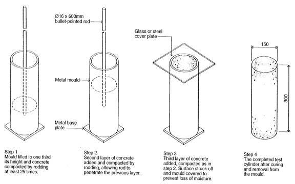
Figure 4: Preparation of a concrete specimen for compression testing
…………………………………………………………………………………………………………………………………………………………
………………………………………………………………………………………………………………………………………………………………………………………………………………………………………
…………………………………………………………………………………………………………………………………………………………
……………………………………………………………………………………………………………………………………………………………………………………………………………………………………………………………………………………………………………………
The ‘design strength’ is the minimum strength required by the designer of a concrete structure. The designer determines the concrete properties that are necessary to ensure that the structure performs in the desired manner during the design stage.
Since compressive strength is usually the most important property required and since most other desirable properties are directly related to it, it is usual for the designer to specify the minimum compressive strength required. This is usually stated as the compressive strength usually achieved at 28 days after setting.
The mix designer must design a mix which will produce concrete with a strength in excess of the design strength for the following reasons:
Generally, a target strength 33% higher than the design strength meets the requirements of the building codes.
In writing the specification to ensure that the concrete has the properties required, the designer has two alternatives:
The designer specifies the minimum compressive strength required in the concrete and the age at which the concrete should have this strength, usually 28 days. This is the usual method for specifying concrete, except if special properties are needed.
In this case, the designer specifies the materials to be used and the proportions to be used. This would usually only be the case if special properties are needed for the concrete.
Designers use knowledge and experience as a basis for ensuring that concrete of the desired strength is produced, and the job supervisor is responsible for the correct materials being used in the specified proportions. The responsibility for the concrete strength and other properties remains with the designer, not the supplier who only guarantees that the mix is in accordance with the designer’s mix specification.
All materials, including water, should be accurately measured to ensure that concrete of uniform quality is produced.
The method used to measure the quantities of different materials required for a mix is called batching by mass. Mass batching is very accurate and reduces the danger of variations of quality of concrete between one batch and another.
Batch proportions are often specified in relation to the bag of cement. For example, one 40 kg bag of cement is specified to so many kilograms of coarse aggregate and so many kilograms of fine aggregate with perhaps 20 litres or 20 kg of water. Even though the solid materials are measured by mass, it is quite common for water to be measured by volume from a graduated tank above the mixer.
Provided that the tank is accurately graduated there is no loss of accuracy as 1 litre of water has a mass of 1 kg and is not subject to variation.
With mass batching, there is no need to make allowance for the bulking of damp sand but allowance must be made for the non–absorbed water held by the aggregates as this moisture forms part of the mixing water.
Equipment for mass batching ranges from simple inexpensive platform scales to large and elaborate types, while some large types of concrete mixers have mass batching devices built into them.
Volume proportions are always specified on the assumption that the aggregates are loose packed and dry.
Most aggregates contain some moisture and sand exhibits a property described as ‘bulking’ when moist; that is, sand when moistened increases in volume.
This property makes sand difficult to gauge accurately by volume measurement and is, in fact, the principal reason why batching by mass rather than by volume is the preferred method.
The aim of mixing concrete is to obtain a uniform mixing of all the concrete materials and to ensure that each particle of aggregate is adequately coated with cement paste.
There are four types of batch mixers:
All except the smallest of batch mixers incorporate loading skips and water tanks with a gauging device. Large mixers may also incorporate built–in mass batchers.
These mixers are particularly common in the small portable sizes (down to 0.06m³ capacity) and a few large models are in use.
The drum is conical in shape and is tilted into different positions for mixing and discharging. Blades inside the drum continually circulate the concrete materials as the drum rotates.
This is the type used around a building site, particularly by bricklayers and blocklayers.
This type of mixer ranges in size from about 0.14 m³ to 3 m³.
It consists of a cylindrical drum revolving about a horizontal axis. The concrete materials are fed by means of a mechanically operated skip through one end of the drum and the mixed concrete is discharged through the other end.
As the drum rotates, blades fixed to the inside of the drum pick up the concrete materials, roll them over and drop them from the top of the drum. The concrete is discharged by inserting a chute to pick up the concrete as it falls within the mixer.
Pan type mixers consist of a cylindrical pan which rotates about a vertical axis. The size range starts with small mixers of 0.43 m³ capacity. These are commonly used by manufacturers of concrete products.
Mixing is achieved by one or more sets of paddles which rotate, also on a vertical axis, within the pan. Pan type mixers are very efficient in mixing very stiff mixes which are difficult for the other types of mixers.
Continuous mixers consist of a cylindrical mixing drum which, when fed with a steady supply of materials at one end, discharges a continuous supply of concrete at the other end.
Dry materials are fed into the mixing drum by means of spiral conveyors while the flow of mixing water is regulated from a tank above the mixer.
The concrete produced by a continuous mixer will not have the same degree of quality control as is possible to produce with a mass batch mixer because the spiral conveyors proportion the materials by volume – adjustments being made by altering the speed of the conveyor.
When the mixer is loaded by a skip it is generally considered best if all the materials are loaded simultaneously. This can be done by spreading each material in a layer in the skip. Spread the coarse aggregate first, then the cement and finally the fine aggregate. This prevents the cement being lost by wind or by the coarse aggregate being placed on top of it. The water feed should be started just before the dry materials and should proceed uniformly until just after the dry materials are added completely. Too rapid a flow of mixing water into the mixer can cause ‘balling’ of the cement.
Increasing the speed of the mixer above that recommended by the maker decreases rather than increases its efficiency. It does not allow sufficient time for the concrete to fall from the blades and as a result, the concrete tends to be carried around without changing its position in the drum.
For the general range of mixers, about 30 revolutions of the drum are sufficient for thorough mixing. Most mixers operate at between 15 and 20 revolutions per minute.
Short mixing times, although increasing production, produce patchy, non-uniform concrete.
Excessive mixing is generally uneconomical and may cause undesirable grinding of the aggregates particularly if they are on the soft side.
The minimum mixing time allowed by AS3600–2001 Concrete Structures is 1½ minutes.
Premixed concrete is used almost universally on residential building sites. The use of premixed concrete has advantages which include:
Premixed concrete is controlled by AS1379–1997 Specification and Supply of Concrete, which should be referred to for information on methods of ordering, mixing and delivery.
The slump of a batch of concrete at the time of discharge should be expressed as the average of two tests, one on concrete sampled at the one–quarter point of the batch volume and the other on concrete sampled at the three–quarter point.
The concrete should be considered to comply with the specified slump if:
The care taken in the production of good quality concrete is to some extent nullified unless the mixed concrete is transported from the mixer to the forms, placed and compacted satisfactorily.
|
Refer to the reference book ‘Guide to Concrete for Housing’ (free publication by the Cement and Concrete Association of Australia) as previously mentioned at the beginning of this section for information about these topics |
Irrespective of the methods used to transport, place and compact the freshly mixed concrete, the following requirements are basic to good practice:
Stiffening of concrete begins as soon as the cement and water are intermingled. This stiffening increases with time, and therefore, the time which elapses after mixing has an adverse effect on the workability of the mix.
Under normal conditions, the amount of stiffening which takes place in the first 30 minutes after mixing is not significant, and if the concrete is kept agitated, up to 1½ hours can normally be allowed to elapse between mixing and compacting.
Concrete is designed to have a workability which will allow it to be fully compacted with the equipment available. If it is allowed to dry out during transportation or placing, it will lose workability and full compaction may not be possible.
Segregation can occur if unsuitable methods are used to transport, place and compact plastic concrete and results in the hardened concrete being non-uniform with weak and porous honeycomb patches.
The strength, durability and impermeability of the hardened concrete all depend on the concrete being fully compacted in the forms. Inadequate compaction results in an appreciable loss of strength.
There are several methods of transporting concrete:
These are the most basic of the vehicles used in this country for transporting concrete but are still in considerable use.
They are particularly suited for smaller jobs and for larger jobs with short hauls. The number of barrows should be sufficient to take the full mix from the mixer in order to minimise wastage of time and avoid confusion.
The hoist is a commonly used means of elevating concrete. Proprietary hoist towers ranging in height from about 4.5 m to
45 m can be made. Hoists can operate an elevating platform onto which one or two barrows of concrete can be wheeled.
Trucks are in general use for transporting concrete from a central mixing plant to scattered jobs or to various parts of a large project. In ordinary trucks, wet concrete is liable to segregate and dry mixes are liable to compact. Concrete should not be hauled over long distances (preferably not more than 3 km to 5 km) in tip trucks and the like.
Premix firms have overcome the problem of segregation during transport by the use of agitator trucks for wet mixes and by truck-mounted mixers which transport a dry batch and mix it when approaching the site.
Unless special care is taken to ensure that the discharge is vertical at the end of the chute and that long chutes are adequately protected to prevent drying out, this can be one of the most unsatisfactory methods of transporting concrete.
The slope of chutes should be sufficient to allow the flow of the lowest slump concrete being used on the job. A baffle at the end of the chute should direct the concrete into a vertical downpipe at least 600 mm long to prevent segregation of the concrete on discharge from the chute.
Pumps and pipelines enable concrete to be transported across congested sites and where space is limited. The maximum horizontal distance concrete can be pumped is 500 m.
Vertical pumping in excess of 120 m may be achieved but heights are normally kept below 30 m.
Maximum length cannot be combined with maximum height.
Curves and rises should be limited as they reduce the maximum pumping distance.
The output of a conventional 100 mm pump varies between about 10 and 100 m³ per hour, depending on type of pump and conditions.
Concrete for pumping must be of medium workability with a slump of 70 mm to 120 mm and must be free from any tendency to segregate. The introduction of fly ash to the concrete improves pumpability and workability of the mix, and therefore adds appreciably to the distance concrete can be pumped.
Certain precautions must be taken when placing concrete, to ensure that:
The following is a summary of some of the most important points of good placing practice.
It is essential that concrete be properly compacted to ensure maximum density. Air holes must be eradicated, voids between aggregate particles must be filled and all aggregate particles must be coated with cement paste.
Thorough compaction results in:
Concrete is usually vibrated to achieve good compaction. There are three types of vibrators:
The immersion vibrator is driven either electrically, mechanically or pneumatically and is probably the most efficient type of vibrator as it vibrates the concrete directly by immersion in the concrete. They are particularly suited to the compaction of large volumes of concrete.
While it is true that concrete increases in strength and other desirable properties with age, this is so only so long as drying is prevented. The hydration of cement is a chemical reaction and this reaction will cease if the concrete is permitted to dry.
Evaporation of water from newly placed concrete not only stops the process of hydration, but also causes the concrete to shrink, thus creating tensile stresses at the drying surface; and if the concrete has not developed sufficient strength to resist these stresses, surface cracking may result. As in many other chemical reactions, temperature affects the rate at which the reaction between the cement and water progresses; the rate is faster at high temperatures than at lower temperatures.
It follows then that concrete should be protected so that moisture is not lost during the early hardening period and should also be kept at a temperature that is favourable to hydration.
Curing methods can be classified as follows:
On flat surfaces, concrete can be cured by building an earth or sand dyke around the perimeter of the concrete surface in which a pond of water is retained. Ponding is not only a very efficient method of preventing water loss from the concrete but also maintains a uniform temperature in the concrete.
Sprinkling can be either continuous or intermittent. If intermittent, care must be taken to ensure that the concrete does not dry between applications of water. A fine spray of water applied continuously through a system of spray nozzles provides a constant supply of moisture and prevents the possibility of cracking or crazing caused by alternate cycles of wetting and drying.
A 50 mm thick layer of earth or sand, straw or hessian or other moisture retaining material spread over the surface of the concrete and kept constantly moist so that a film of water remains on the surface of the concrete throughout the drying period has proved very satisfactory.
Strips of waterproof paper or plastic sheeting spread over the surface of the concrete will prevent the evaporation of the water from the concrete.
The edges of the sheeting should be overlapped and sealed with sand, tape or by weighting down with planks or other heavy objects. An important advantage of this method is that periodic additions of water are not required.
Liquid membrane forming curing compounds sprayed over the surface of moist concrete will retard or prevent the evaporation of moisture from the concrete.
Some curing compounds prevent the bonding of fresh concrete to hardened concrete and should not be used for instance on the base slab of a two-course floor since the top layer may be prevented from bonding.
The adhesion of resilient floor coverings to concrete floors may also be affected by some curing compounds.
Vertical surfaces can be satisfactorily cured by:
For most structural purposes, the curing time for concrete varies from a few days to two weeks according to conditions; for example, lean mixes require longer curing time than rich mixes and temperature affects the curing time as does the type of cement used.
Since all the desirable properties of concrete are improved by curing, the curing period should be as long and as practicable in all cases.
……………………………………………………………………………………………………………………………………………………
……………………………………………………………………………………………………………………………………………………
…………………………………………………………………………………………………………………………………………………………………………………………………………………………………………………………………………………………………………………………………………………………………………………..
……………………………………………………………………………………………………………………………………………………………………………………………………………………………………………………………………………………………………………………………………………………………………………………
………………………………………………………………………………………………………………………………………………………………………………………………………………………………………………………………………………………………………….
These are manufactured from graded sand, aggregate, Portland cement and water; fly ash is often used as a cementing agent. They are made in a variety of solid and hollow shapes but in standardised metric sizes, so that a block or half block, with the addition of 10mm of mortar, measures whole units of 100mm or 50mm.
Brick type |
Length |
Height |
Width |
|
390 |
190 |
290, 190, 140, 90 |
|
390 |
90 |
190, 140, 90 |
|
290 |
90 |
90 |
|
230 |
76 |
110 |
Calcium silicate or sand-lime bricks are also used, though not yet in the same quantities as clay bricks.
They are usually which or grey in colour, but their physical characteristics are different.
Reinforced concrete
Concrete, like any other building material, has limitations, mainly because of the fact that while it is strong in compressive strength, it is comparatively weak in tensile strength. To overcome this weakness in tension, concrete which is to be subjected to tensile stresses is reinforced with steel bars or mesh which is placed so that it will resist such stresses.
The designing and detailing of reinforcement is the job of the designing engineer and will not be dealt with in any great detail here, but it is important that those who supervise the fixing of reinforcement on the job have an appreciation of the basic principles of reinforced concrete. They can then understand why it is necessary that reinforcement be correctly handled and fixed in the positions indicated on the job drawings.
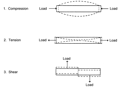
Figure 5: Types of stress found in a structure
Reinforced concrete is designed to combine the concrete and steel into one structural entity in such a way as to make the best use of the characteristics of each of these materials.
The aim of reinforced concrete design is to combine the steel reinforcement with the concrete in such a manner that just enough steel is included to resist the tensile stresses and excess shear stresses, while the concrete is used to resist the compression stresses.
Steel and concrete combine together successfully because:
A broad understanding of stresses and the methods of indicating the particular stress on drawings is essential.
In order to be effective, the tensile reinforcement must be prevented from sliding in the concrete. The adhesion or bond between the concrete and the steel is related to the surface area of the steel embedded in the concrete.
Adequate anchorage is effected by extending the rods past the critical points (where no longer required to resist tensile and shear stresses) and by the use of:

Figure 6: Positioning of main reinforcement to resist tensile stresses in beams
In its plastic state, concrete can be readily moulded into any desired shape. As any inaccuracy or blemish in the formwork will be reproduced in the finished concrete, it is essential that the forms be designed and constructed so that the desired size, shape, position and finish of the concrete is obtained.
Although the formwork is a temporary structure, it will be required to carry heavy loads resulting from the mass of the freshly placed concrete and construction loads of materials, workers and equipment. The formwork must therefore be substantial enough to carry these loads without fear of collapse or deflection, and within the confines of AS3610 Formwork for Concrete.
As the cost of formwork can amount to about one-third of the total cost of a concrete structure, efficiency in its construction can become an important factor in the overall economy of the job.
The guiding principles for the production of good formwork are:
First quality formwork should be:
For economy, formwork should be:
The field supervisor’s work falls into four categories:
Some of the deficiencies which can lead to form failures are:
Points which are related to workmanship are:
Formwork can be constructed in many different types of materials. Details about each type follow.
Partially seasoned softwoods, such as oregon or pine, dressed where in contact with the concrete, make good formwork. Fully seasoned timber will swell excessively when wet and green timber will warp and shrink during hot weather.
Varying in thickness from 5 mm to 20 mm, plywoods give a large area of joint–free surface. Plastic coated plywood (plasply) can be used to give a smooth grainless surface to the finished concrete. Plywood can be bent to produce curved surfaces.
Hardboard has many of the features of plywood but requires more support and cannot be curved so easily.
Steel is relatively costly but it can withstand repetitive reuse. Steel framing and bracing can be used in conjunction with timber and plywood panel systems. There are a number of proprietary steel formwork systems available.
All debris, particularly chippings, shavings and sawdust, must be removed before the concrete is placed and the surfaces which are to be in contact with the concrete must be cleaned and thoroughly wetted or, alternatively, treated with a suitable composition. Compositions that have not been approved by the engineer or architect must not be used.
Temporary openings must be provided at the bases of columns and wall forms and at other points where necessary to allow cleaning and inspection immediately before the placing of the concrete.
Any material used as a surface coating for forms must:
A number of form oils suitable for timber forms are marketed commercially. These are designed to penetrate the surface to some extent and leave the surface of the form only slightly greasy to the touch. For plywood, apart from the commercially produced oils, a mixture of linseed oil and kerosene is satisfactory.
Plywood may also be coated with shellac, lacquer, resin-based products or plastic compounds which almost totally exclude water from the plywood, thus preventing the grain from rising. Such coatings require little or no oiling.
Form oils suitable for timber forms are not always suitable for metal forms. Paraffin-based form oils and petroleum-based oils blended with synthetic castor oil, silicone or graphite have proved successful on metal forms.
Forms can usually be safely stripped when the concrete has developed about two-thirds of its 28-day strength. Vertical forms can generally be removed before the forms to the soffits of beams and slabs.
The time of the removal of forms is generally specified by the architect or engineer in the contract documents or made subject to this person’s approval because of the danger to the structure if forms are stripped before the concrete has developed sufficient strength.
However, the earliest possible removal of forms is desirable for the following reasons:
Remember, safety is paramount, and it is much better to be sure than sorry.
Where stripping times have not been specified, Table 1 may be used as a guide to appropriate stripping times when using normal Portland cement.
Location and type of formwork |
Average temperature of concrete during the period before stripping |
|
21°C to 32°C Days |
4°C to 21°C Days |
|
Beam sides, walls and unloaded columns |
1–2 |
2–5 |
Heavily loaded columns, tunnel linings supporting unstable material, and other heavily loaded structures |
7–10 |
10–14 |
Slabs, including flat slabs and flat plates, with props left under |
3–7 |
7–20 |
Removal of props from under slabs |
7–14 |
14–21 |
Beam and girder soffits (with props left under) and arch soffits |
7–10 |
10–14 |
Removal of props from under beams |
10–14 |
14–28 |
Table 1: Times for stripping formwork and supports
It is economical for the structural concrete to form the surface finish. Where special characteristics such as smoothness, pattern, texture, intricate detail and so on are required, extra special care must be taken in the selection of form materials and in the form construction.
Most sheathing and lining materials are available in grades smooth enough to produce a blemish free concrete surface. The correct choice of form oil is important in achieving the desired smoothness.
A surface simulating wood grain can be produced by casting the concrete against a plywood form liner which has had the grain revealed by wire-brushing or sand-blasting. Sometimes an exposed grain plywood is available ready–made for this purpose.
To produce a rough board marked surface, sawn boards are used for sheathing. These boards may be sprayed with ammonia to raise the wood fibres and accentuate the grain markings.
These finishes are obtained by lining the forms with liners such as striated plywood, rubber matting and moulded plastic. The liners are either nailed or fixed with a waterproof glue to the inside surfaces of the forms.
Interruptions to the placing of concrete will inevitably occur when pouring large quantities. Irrespective of the length of these interruptions, if the concrete is allowed to stiffen to the extent that it cannot be worked, then a joint must be made. Other cases will occur when it is necessary, for structural reasons, to break the continuity of placing and to form a joint.
Joints can be of two general types:
In practice, it is very difficult to obtain a perfect bond at a joint and a plane of weakness will always occur at a construction joint. For this reason, they should be avoided wherever possible.
While unscheduled interruptions are often unavoidable during placing, making an unplanned construction joint necessary, some breaks in the continuity of placing may be foreseen.
These may be either in the design stage or just before commencement of construction, thus allowing the position of many joints to be planned.
Good planning will aim to interrupt placing in a position suitable for a control joint and so eliminate the need for a construction joint.
Where construction joints are necessary in structural members they should be made where the shear forces are at a minimum. The joint should be at right angles to the axis of the member so that axial forces act normally to the joint and do not tend to cause sliding along a weakened plane.
Concrete for columns should be poured continuously to just below the soffit of the beam, drop panel or capital, and the concrete left for at least two hours to settle before fresh concrete is placed. The whole floor system around the head of the column should then be cast in one operation after suitable preparation of the joint.
Construction joints in beams should be made in the middle third of the span and on no account should they be made at or near the supports or over any other beam, column or wall since shearing stresses are usually very high at these positions.
When a construction joint is required in a floor slab it should be made near the middle of the span.
When making a construction joint in a beam or slab, the concrete must not be allowed to assume its natural angle of repose, but should be taken up to a suitable stop board so as to form a vertical joint.
To assist the transfer of load across the joint, either dowels or a keyway to aid mechanical bonding may be used at about mid-depth of the beam or slab. This is recommended in sections over 150mm deep.
Reinforcement must not be cut at a construction joint but must be left continuous in the member.

Figure 7: Making a vertical construction joint
The correct method of preparation and making of construction joints is detailed in AS3600 1994 Concrete Structures Code.
A correctly made horizontal construction joint in a wall should not require sealing. However, if the joint is to be in contact with water and particularly if subjected to hydraulic pressure, effective sealing will be necessary because of the tendency of the joint to open up as the concrete shrinks. This can best be carried out by using a water stop.
PVC water stop membranes extending into the concrete equally each side of the joint and welded or glued together at the ends to form a continuous diaphragm are commonly used.
A vertical plane of weakness is purposely formed in the slab or wall. The bond between new and existing concrete at a control joint must be broken.
As concrete sets, hardens and dries out, it shrinks. If no provision is made to relieve the drying-shrinkage tensile stresses within the concrete, cracking will occur when these stresses exceed the tensile strength of the concrete. If the concrete is completely unrestrained, cracking will not occur, but very few structures are completely unrestrained.
A contraction joint is a joint made so that the concrete is free to shrink away from the joint while all other relative movement across the joint face is prevented. In a horizontal member, vertical movement is controlled by forming a keyed joint or by using non-ferrous dowels with one end capped and coated so that they are free to slide.
Contraction joints are most needed in unreinforced concrete structures because reinforcement considerably increases the tensile strength of concrete, restrains overall shrinkage movement and prevents the formation of large shrinkage cracks.
Contraction joints should be located where it can be expected that the severest concentration of tensile stresses will occur.
Such locations are:
A dummy contraction joint is a plane of weakness built into a structure by means of a groove, either sawn or formed with a grooving tool.
This joint functions as a contraction joint by localising shrinkage cracks to beneath the groove. The irregularity of the crack serves to transfer loads across the joint and prevents relative movement in the plane of the joint.
Since this type of joint is an alternative to a full depth contraction joint, the location should be the same as for contraction joints.
An expansion joint is formed by creating a gap between the two surfaces of the concrete to allow for expansion. The gap is usually filled with a compressible filler and all relative movement in the plane of the joint is prevented.
Expansion joints are generally provided in structures exceeding
30 m length, in unreinforced or lightly reinforced road pavements and as sliding joints between a roof slab and a supporting wall.

Figure 8: Various joint in concrete slabs
Concrete is a composite material comprising Portland cement and water (known as the paste) and aggregate. Aggregate occupies approximately 75% of the volume of the concrete while the paste and voids occupy the remainder. General purpose (type GP) is the most commonly used cement in the building industry.
Water and aggregates used in concrete should be free of any deleterious materials, and aggregates should also be hard and durable.
Compressive strength is the common criteria of concrete quality and is dependent on the water/cement ratio. Concrete is tested on site for consistency (the slump test) and off site, following strict curing procedures, to determine the compressive strengths at 28 days (the compression test).
In residential building, concrete is delivered to the site ‘ready mixed’ in nearly all cases except where only a small quantity is required and then will usually be mixed on site using bags of premixed cement and aggregate.
Good practice for the transport and placing of concrete must be followed to ensure a strong, dense and watertight product. It must be properly cured to allow an increase in strength with age. The first seven days are particularly important in allowing the chemical process of hydration to proceed unheeded.
Reinforced concrete combines steel and concrete, making use of the best properties of both materials to produce a product used universally on virtually all building projects. The tensile strength of the steel is combined with the compressive strength of concrete as a building material. This strength, combined with its ability to assume any desired shape and its resistance to fire, makes concrete a very valuable and adaptable material for the building industry.
………………………………………………………………………………………………………………………………………………………………………………………………………………………………………………………………………………………………
………………………………………………………………………………………………………………………………………………………………………………………………………………………
………………………………………………………………………………………………………………………………………………………………………………………………………………………………………………………………………………………………
Source: http://bctcwagga.riverinainstitute.wikispaces.net/file/view/Unit+3+Mortars+Concrete+and+Concrete+Products.doc
Web site to visit: http://bctcwagga.riverinainstitute.wikispaces.net/
Author of the text: indicated on the source document of the above text
If you are the author of the text above and you not agree to share your knowledge for teaching, research, scholarship (for fair use as indicated in the United States copyrigh low) please send us an e-mail and we will remove your text quickly. Fair use is a limitation and exception to the exclusive right granted by copyright law to the author of a creative work. In United States copyright law, fair use is a doctrine that permits limited use of copyrighted material without acquiring permission from the rights holders. Examples of fair use include commentary, search engines, criticism, news reporting, research, teaching, library archiving and scholarship. It provides for the legal, unlicensed citation or incorporation of copyrighted material in another author's work under a four-factor balancing test. (source: http://en.wikipedia.org/wiki/Fair_use)
The information of medicine and health contained in the site are of a general nature and purpose which is purely informative and for this reason may not replace in any case, the council of a doctor or a qualified entity legally to the profession.
The texts are the property of their respective authors and we thank them for giving us the opportunity to share for free to students, teachers and users of the Web their texts will used only for illustrative educational and scientific purposes only.
All the information in our site are given for nonprofit educational purposes
