In order to become an expert in technical drawing you must have a good knowledge of basic geometry. There are two forms of geometry you need to understand:
A line is bisected when it is divided exactly into two equal parts. To bisect a line follow the example shown in Drawing 1 of Figure 2.
Perpendiculars to Lines
Two lines are perpendicular to each other if they are at a right angle (90 degrees) with each other.
To Draw a Line Perpendicular to a Line from a Point on the Line
DRAWING 2 - Figure 3
- Draw the line AB 80 mm long. Mark the point C 40 mm above the line and 25 mm from the left hand end.
- Set a compass, centred at C, to a suitable size so as to draw an arc which cuts the line AB at E and F.
- Re-set the compass and, with the compass centred at E, then at F draw the crossing arcs G.
- Draw a line CG. The line CD is perpendicular to AB.
DRAWING 2 - Figure 3
- Draw the line HJ 70 mm long. Mark the point K 30 mm along HJ from J.
- With a compass centred at K draw arcs across the line HJ to give the points M and N.
- Re-set the compass and, with the compass centred first at M, then at N draw the crossing arcs L.
- Draw the line KL. The line is perpendicular to line HJ.
Drawing 5
Draw the line UV at 45 degrees to the horizontal. Mark the point W on UV. At W construct a line perpendicular to the line UV.
Complete your drawing by adding border lines and a title block. The border line is set in 10mm from the paper edges. The lettering in the title block should be 6mm high. Use capital letters.
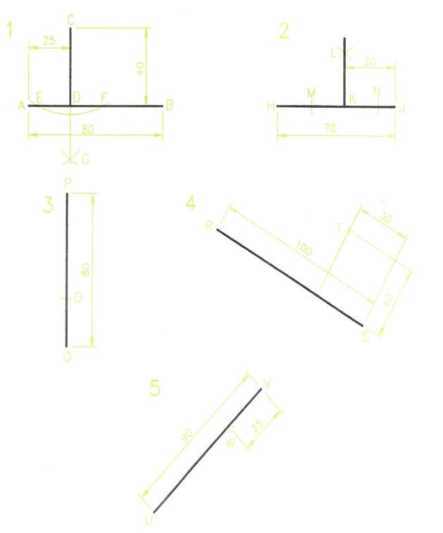
Figure 3 - Perpendiculars to Lines
Parallel Lines
Lines are parallel to each other if their distances apart are the same throughout their lengths.
Drawing Parallels with Tee Square and Set Squares
Figure 4
- Drawing 1- draw a line with your Tee square.
- Draw lines parallel to the first line and at a measured distance of 10 mm from each other.
- Drawing 2 - with a 45, 45 set square draw a series of parallel lines 15 mm distance from each other.
- Drawing 3 - with a 60, 30 set square draw a series of lines parallel to each other and at a distance of 20 mm apart.
Drawing Parallels with the Aid of a Compass
- Drawing 4 - Draw a line AB 90 mm long.
- Set a compass to 20 mm.
- With the compass centred at any two points on the line, draw the arcs C.
- Draw a line DE touching the two arcs.
Note: this is not an accurate method, but is useful in technical drawing when drawing parallels at angles which are not Tee or set squares angles.
An Accurate Compass Method
- Drawing 5 - Draw the line FG 75 mm long.
- The line HL is to be parallel to FG and 30 mm distance from it.
- With the aid of your ruler mark H at a distance of 30 mm from FG.
- Set a compass to the radius GH and strike an arc.
- Without re-setting the compass and centred at F strike an arc at L.
- Re-set the compass to FH and strike an arc.
- Without re-setting the compass and centred at G, strike an arc crossing the previous one at L.
- Join HL - which is parallel to FG.
Note: this is a more accurate method than that shown in Drawing 4.
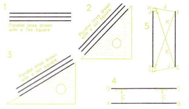
Figure 4 - Parallel Lines
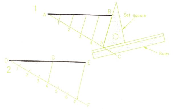
Figure 5 - Dividing a Line into Parts
Dividing a Line into Parts
The method shown can be used either for dividing a line into parts of equal lengths or into lines which are proportional in length to each other.
Dividing a Line into Parts of Equal Length
- Drawing 1 (Figure 5) - Draw line AB 93 mm long with a Tee square.
- Draw line AC from A at any angle to AB. The angle should be similar to that shown in Figure 5.
- Set a compass to about 20 mm and with it, step off five equal spaces along line AC - giving the points 1 to 5.
- Set up a ruler with a set square along its edge, so that one edge of the set square is along the line B5.
- Hold the ruler firmly on to the paper; slide the set square along the ruler until its edge is at point 4 on line AC. Draw a line to touch the line AB. This line is parallel to line B5.
- Draw other parallels in the same way through points 1, 2 and 3 on AC.
- AB is divided into 5 equal parts at the points where the parallel lines touch AB.
Dividing a Line into Proportional Parts
- Drawing 2 (Figure 5) - Draw line DE 147 mm long.
- Draw line DF at any suitable angle.
- Set a compass to about 20 mm and with it mark off the 7 equal spaces along DF.
- Draw line E7 as indicated in previous exercise.
- Using the same method of drawing parallel lines as was used in Drawing 1, draw a parallel to E7 through point 4 on line DF.
- DG is now 417ths of DE.
Note: A proportion (or ratio) such as the length DG in relation to DE is shown in the following manner: DG:DE = 4:7
Drawing Scales
Many technical drawings will be drawn to scales in which the drawing is either smaller or larger than its correct full-size. When drawing to a scale all parts of the drawing are reduced or enlarged by the scale factor. Common scales in use with the metric system of measurement are:
- In engineering drawings - 1:2; 1:5; 1:10; 2:1; 5:1.
- In building drawings - 1:20; 1:50; 1:100; 1:200.
Drawing 1
(Figure 6) - Constructing a scale of 1:5. Each 1 mm on the drawing represents 5 mm on the item being drawn.
- Draw line AB 150 mm long. Draw CD at 5 mm parallel to AB.
- Divide AB into 3 equal parts - measuring with a ruler. Draw verticals 10 mm high at the division points.
- Divide the first 50 mm AE of AB into 10 equal parts.
- Complete the scale as shown in Figure 6.
Note: two examples of taking scaled measurements from the scale are shown in Figure 6. Examine the scale and you will understand why the scale is numbered with 0 being at the first division point along AB.
Drawing 2
(Figure 6) - Constructing a scale of 60 mm represents 1 metre.
- Draw FG 240 mm long. Then draw HJ at 5 mm parallel to EF.
- Divide FG into 4 equal parts and draw verticals at the divisions 10 mm high.
- Divide the first 60 mm of FG into 10 equal parts.
- Complete the scale as shown in Figure 6.
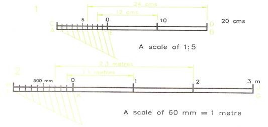
Figure 6 - Drawing Scales
Circles and Parts of Circles
Figure 7 gives the names of parts of a circle:
- Circumference: the actual line of the circle.
- Arc: part of the circumference of a circle.
- Chord: a straight line, with each end touching the circumference.
- Diameter: the longest possible chord of a circle. A line passing through the centre of the circle, with both ends touching the circumference.
- Radius: any of the straight lines from the centre of a circle to its circumference. The radius of a circle is half the diameter of the circle.
- Sector: part of a circle enclosed by two radii and the arc joining the ends of the two radii.
- Segment: part of a circle enclosed by a chord and the arc touching both ends of the chord.
- Protractor: a protractor is illustrated in Figure 8. Protractors are for drawing or measuring those angles that cannot be easily drawn with a Tee square and set squares. Protractors are usually made to construct or measure angles from 0 degrees to 180 degrees, from either the left hand end or the right hand end of the protractor. Protractors are also made in a full circle pattern. These will measure or construct angles up to 360 degrees, without having to turn the protractor upside down. Semicircular protractors can, of course, also be used for constructing and measuring angles greater than 180 degrees.
Degrees in a Circle
Figure 8 shows that a full circle contains 360 degrees; a semi-circle contains 180 degrees and a quadrant (a quarter of a circle) contains 90 degrees. An angle of 90 degrees is a right angle.
Circles and Angles
- Drawing 1 of Figure 9. Set a compass to 40 mm and draw a circle. Add its centre lines, passing through the centre' of the circle as shown.
- Without changing the setting of the compass, and with centre A, strike an arc across the circle to give point 1.
- With centre 1, strike another arc across the circle to obtain point 2.
- Continue in the same way until it is found that with the compass centred at point 5, the arc 6 is crossing the circle at the start point A.
Note: no matter what the size of the circle, its radius can always be stepped off 6 times around the circumference. The actual length of the circumference is 2Jt times the radius.
Circumference = 2πR.
Constructing Angles of 60 and 120 Degrees
- Drawing 2 - Figure 9. Draw a line BC 50 mm long.
- Set a compass to about 30 mm and with centre B draw an arc crossing BC at D.
- Without altering the compass and centred at D draw an arc crossing the first arc at E.
- Draw BF through the intersection of the two arcs.
- The angle CBF is 60 degrees.
Note: by stepping of the radius of a circle exactly 6 times around its circumference.
- HGL of 120 degrees (Drawing 3) step off the radius twice along the arc from J.
To Bisect an Angle
- Drawing 4 - Figure 9. Draw any angle.
Draw any arc PQ. Set compasses to a sensible size and with the compass centred first at P, then at Q draw crossing arcs at R.
- Draw MS passing through R. The angles NMS and SMO are equal.
Angle in a Semi-Circle
The angle contained in a semi-circle is a right angle.
All the angles in Drawing 5 - SUT, SVT and SWT are right angles.
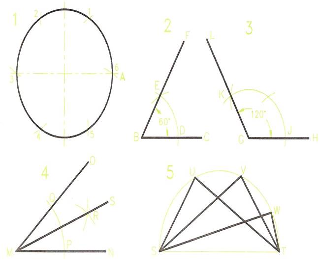
Figure 9 - Circle and Angles
Finding the Centre of Arcs and Circles
The bisector of any arc passes through its centre. It follows that if any two arcs of an arc or a circle are bisected, they must intersect at the centre of the arc or circle.
- Draw any arc - Drawing 1 Figure 10.
- Mark off any three points C, D and E on the arc.
- Bisect the two arcs CD and DE. The bisection lines cross at 0, which is the centre of the arc.
- Check that you have found the correct centre by centring a compass at 0 and attempting to complete the circle of which the arc is a part.
- Draw any circle - Drawing 2 Figure 10.
- Mark off any three points F, G and H on the circle's circumference.
- Bisect the arcs FG and GH. The bisection lines cross at 0 - the circle centre.
Acute and Obtuse Angles
- Drawing 3 of Figure 10 is an acute angle - it is less than 90 degrees.
- Drawing 4 of Figure 10 is an obtuse angle - it is between 90 degrees and 180 degrees.
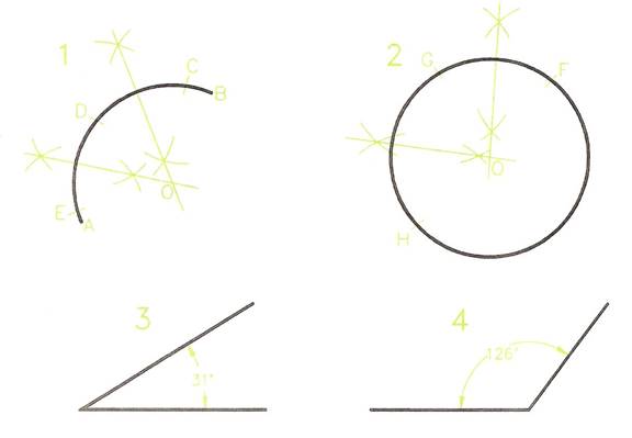
Figure 10 - Finding the Centre of an Arc and a Circle
Constructing Angles
- Drawing 1, Figure 11 - Construct an angle of 60 degrees. Bisect to obtain 30 degrees.
- Drawing 2 - Construct an angle of 60 degrees.
Bisect to obtain 30 degrees. Bisect to 15 degrees.
- Drawing 3 - Construct an angle of 120 degrees.
Bisect the angle between 60 degrees and 120 degrees to obtain an angle of 90 degrees.
- Drawing 4 - Construct an angle of 90 degrees.
Bisect it to obtain an angle of 45 degrees.
- Drawing 5 - Construct an angle of 90 degrees.
Bisect between 90 and 180 degrees to obtain an angle of 135 degrees.
- Drawing 6 - Bisect the angle between 90 and 120 degrees to obtain an angle of 105 degrees.
Constructing an Angle with the Aid of a Protractor
Figure 12 shows the method of constructing an angle of 74 degrees with the aid of a protractor.
- Draw the base line of the angle.
- Place the protractor in position on the line with the protractor cross lines on the end of the line.
- Make a light pencil mark against the figures of the angle to be drawn.
- Draw a line from the end of the base line through the pencil mark.
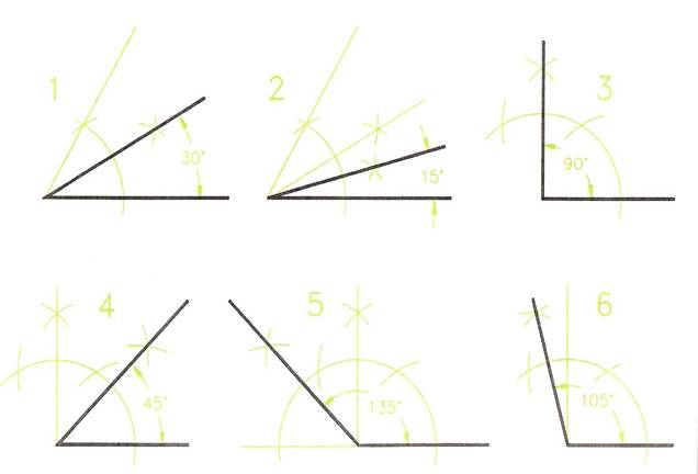
Figure 11 - Constructing Angles
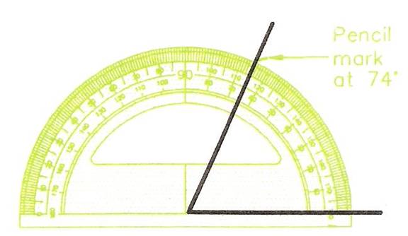
Figure 12 - Constructing an Angle with the Aid of a Protractor
Further Basic Plane Geometry
Introduction
The more advanced geometry, involving the use of these features, is given to complete the basic geometry necessary for those wishing to become expert in the construction of accurate technical drawings. Thus the construction of triangles, polygons of various types, circles in relation to triangles and polygons, tangents and ellipses are included in this chapter. These are the basic construction tools of technical drawings.
Triangles
- Triangles have three sides.
- Triangles have three angles. The sum (adding together) of the three angles always gives 180 degrees.
Types of Triangle
There are four types of triangle - shown in Figure 13.
- Equilateral - All sides are of equal length.
All angles are of equal size = 60 degrees.
- Isosceles - Two angles are of equal size.
Two sides are of equal length.
- Right-angle - One angle is a right-angle = 90 degrees.
- Scalene - all sides are of different lengths.
All angles are of different sizes.
Two main types of scalene triangle:
Acute - all angles are acute = less than 90 degrees
Obtuse - one of the three angles is obtuse = between 90 and 180 degrees
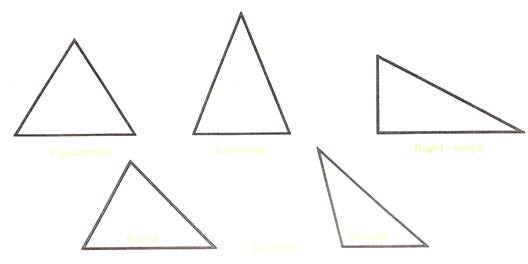
Figure 13 - Types of Triangles
Parts of Triangles
Figure 14 shows the names of the parts of triangles.
- Triangle vertices are often lettered, using capitals, when the triangle may be, for example triangle ABC.
- If sides are lettered, lower case is used, e.g. a and band c.
- The angles of triangle ABC are BAC, ABC and ACB - the middle letter being the angle where the letter is positioned.
- The base of a triangle is the side on which it is standing.
- The altitude is the vertical height above the base.
- The term hypotenuse is only used with reference to right-angle triangles.
- The vertical angle is the angle opposite the base.
- Note the term vertex. Its plural is vertices.
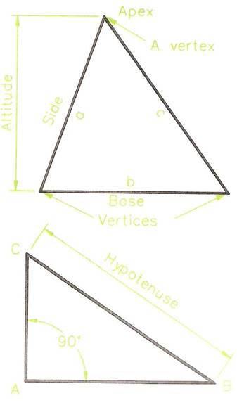
Figure 14 - Parts of Triangles
Constructing an Equilateral Triangle
Figure 15 shows two methods of constructing an equilateral triangle:
- With the aid of a 30, 60 set square, using the 60 degree angle. Start by drawing the base, AB, and then draw lines, meeting at C, at 60 degrees from each end of the base with the aid of the set square.
- Strike off compass arcs with the compass set to the length of the side. Thus in the lower of the two drawings of Figure 15, the side length of the equilateral triangle is 60 mm. Start by drawing the base - a line 60 mm long; then set a compass to 60 mm and strike arcs from each end of the base; draw lines from the ends of the base to the intersection of the two arcs.
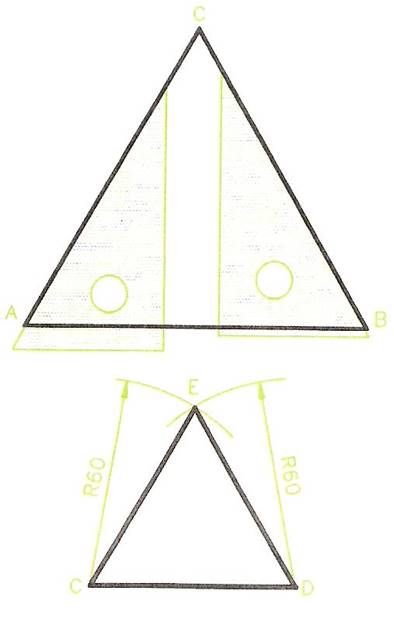
Figure 15 - Constructing Equilateral Triangles
The 3:4:5 Right-Angle Triangle
The upper of the two drawings of Figure 16 shows a triangle with sides in the proportion 3: 4: 5. Such a triangle is always a right-angle triangle. This is because:
The square on the hypotenuse is equal to the sum of the squares on the other two sides.
Taking the 3: 4: 5 triangle:
- The square on the hypotenuse = 5 x 5 = 25.
- The square on the shortest side = 3 x 3 = 9.
- The square on the other side = 4 x 4 = 16; and 9 + 16 = 25.
Thus: if the sides of a triangle are 30 mm, 40 mm and 50 mm long, the triangle is a right-angled one.
If the sides are 27 mm, 36 mm and 45 mm in length the triangle is a right-angled one.
Other 3: 4: 5 triangles are found for example in a triangle ABC, in which AB = 28 mm, BC = 21 mm and AC = 35 mm. And also in triangle XYZ in which: XY = 57 mm, YZ = 76 mm and XZ = 95 mm.
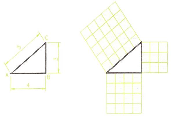
Figure 16 - Right-Angled Triangle
In a right-angle triangle, the square on the hypotenuse is equal to the sum of the squares on the other two sides.
More Triangles
To Construct Triangle ABC
- Draw the base AB, 50 mm long. Set a compass to 70 mm.
- With the compass centred first at A, then at B strike intersecting arcs to give C.
- Join AC and BC to complete the triangle.
Note: triangle ABC is isosceles.
To Construct Triangle DEF
- Draw DE. Set a compass to 60 mm.
- With the compass centred first at D, then at E strike intersecting arcs to obtain F.
- Join DF and EF to complete the triangle.
Note: DEF is another isosceles triangle.
To Construct Triangle GHJ
- Draw GH 85 mm long.
- Set a compass to 90 mm and from G strike an arc J.
- Set a compass to 60 mm and from H strike an arc crossing J.
- Join GJ and HJ to complete the triangle.
To Construct Triangle KLM
- Draw KL 70 mm long.
- With the aid of a protractor construct a 105 degree angle at L, and draw a line from L at that angle.
- Set a compass to 100 mm. With the compass centred at K strike an arc across the arm of the line at 105 degrees from L, to give M.
- Join LM to complete the triangle.
Note: KLM is a scalene triangle, which is obtuse.
To Construct Triangle NOP
- To construct triangle NOP
- Draw NO 90 mm long.
- Draw the angle NOP with a set square.
- Set a compass to 110 mm. With the compass centred at N strike an arc across the 90 degree line from 0 to give P.
- Join NP to complete the triangle.
Note: NOP is a right-angle triangle.
Revision hint: do not erase constructions. They will remind you when you are revising for examinations.
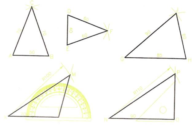
Figure 17 - Triangles
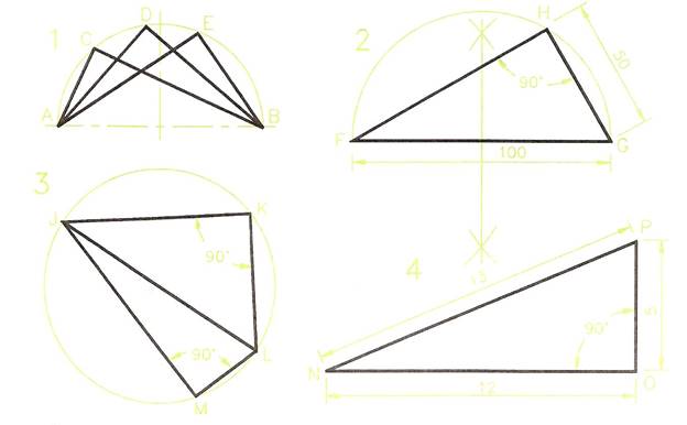
Figure 18 - Right-Angle Triangles
Right-Angle Triangles
Note: the right-angle triangle is an important geometrical figure.
DRAWING 1 - Figure 18.
Constructing the Triangle
DRAWING 2 - Figure 18.
- Draw the base FG 100 mm long.
- Bisect the base FG.
- At the bisection point of FG, draw a semi-circle of radius equal to half FG.
- With a compass set to 50 mm, and centred at G strike an arc across the semi-circle to give H.
- Join GH and FH to complete the triangle.
Note: FHG is a right-angled triangle because the angle at H is an angle within a semi-circle.
A Cyclic Quadrilateral
DRAWING 3 - Figure 18.
If two triangles are drawn within a circle with a common diameter of the circle as a base and with the vertical angles touching the circumference of the circle, they are said to form a cyclic quadrilateral. Quadrilaterals - plane figures with four sides - are described later in this chapter.
Note the following details about the cyclic quadrilateral JKLM.
- The angle LKJ is a right-angle - angle of a triangle in a semi-circle.
- The angle JML is also a right angle for the same reason.
- Because there are 180 degrees in a triangle the sum (addition) of the two angles KJL and KLJ of triangle JKL must be 90 degrees.
- In the same way the sum of the two angles JLM and LJM must also be 90 degrees.
- Thus the sum of the two angles KJM and KLM of the cyclic quadrilateral must be 180 degrees.
From this it can be seen that a feature of cyclic quadrilaterals is that the sum of their opposite angles is always 180 degrees. In fact a quadrilateral must be cyclic if the sum of its opposite angles is 180 degrees.
DRAWING 4 - Figure 18.
The right-angle triangle NOP with its sides in a ratio of 5:12:13 is another example of one in which the square on the hypotenuse the square on the hypotenuse is equal to the sum of the squares on the other two sides.
Triangles and Circles
A Circle Circumscribing a Triangle
DRAWING 1 - Figure 19.
- Construct the triangle ABD in which:
AB = 70 mm; BD = 65 mm: AD = 45 mm.
- Bisect AB and AD. The bisection lines cross at C.
- C is the centre of a circle circumscribing ABD.
- Set a compass to CA (or CB, or CD) and draw the circumscribing circle centred at C.
Notes:
- A circle circumscribes a triangle if its circumference touches the vertices of the triangle.
- When finding the centre C of a circle circumscribing a triangle, the most accurate results will be achieved if the sides of the triangle nearest to a right angle are bisected.
A Circle Inscribing a Triangle
DRAWING 2 - Figure 19.
- Construct the triangle EFG in which:
EF = 90 mm; FG = 50 mm; EG = 95 mm.
- Bisect the angles EFG and FGE to give I.
- I is the centre of the circle inscribing triangle EFG.
- Set a compass to a radius of the perpendicular distance I to any side of the triangle and with centre I draw the inscribing circle.
Notes:
A circle inscribes a triangle if its circumference touches (is tangential to) each side of the triangle.
As with the construction of the circumscribing circle, the most accurate results are obtained if the bisections are made of the two angles of the triangle which are most near to being right-angles.
DRAWING 3 - Figure 19.
- Construct triangle HJK in which:
HJ = 70 mm; JK = 65 mm; HK = 115 mm.
- Bisect the sides HJ and JK and draw the circumscribed circle to HJK.
DRAWING 4 - Figure 19.
- Construct the triangle LMN in which:
LM = 70mm; MN = LN = 80mm.
- Bisect the angles MLN and LMN and draw the inscribed circle to LMN.
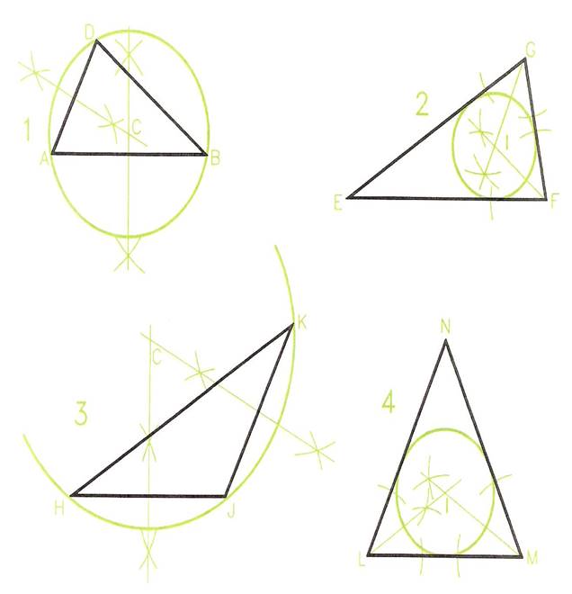
Figure 19 - Triangles and Circles
Types of Quadrilateral
Quadrilaterals are polygons which have four sides and four angles. Quadrilaterals may be irregular or regular. A polygon is regular if all its sides are of equal length and all its angles are of equal size.
Figure 20 and Figure 21 both show a number of different types of quadrilateral.
- Irregular - sides are of different lengths; angles are of different sizes.
- Square - all sides the same length; opposite sides are parallel- in EFGH of Figure 20, EF is parallel to GH and FG is parallel to EH; all angles are right angles = 90 degrees.
- Rectangle - all angles are right angles; opposite sides are of equal length; opposite sides are parallel - in JKLM of Figure 20, JK is parallel to LM and KL is parallel to JM.
- Parallelogram - Each pair of opposite sides are parallel - in ABCD of Figure 21, AB is parallel to CD and BC is parallel to AD; opposite angles are of equal size - in parallelogram ABCD of Figure 21, angle at A = angle at C and angle at D = angle at B; angles on the same side add up to 180 degrees - angle A + angle B = 180 degrees and so on.
- Rhombus - a parallelogram in which all sides are the same length; opposite angles are equal - in EFGH of Figure 21, angle at E = angle at G and angle at F = angle at H; the diagonals of a rhombus bisect each other at right angles.
- Trapezium - One pair of opposite sides is parallel- in the example JKLM of Figure 21, JK is parallel to LM.


