A summary handout of electrical and pneumatic component symbols commonly used in circuit representations
Electrical Symbols:
Source: http://www.kpsec.freeuk.com/symbol.htm
Wires and connections |
||
Component |
Circuit Symbol |
Function of Component |
Wire |
|
To pass current very easily from one part of a circuit to another. |
Wires joined |
|
A 'blob' should be drawn where wires are connected (joined), but it is sometimes omitted. Wires connected at 'crossroads' should be staggered slightly to form two T-junctions, as shown on the right. |
Wires not joined |
|
In complex diagrams it is often necessary to draw wires crossing even though they are not connected. I prefer the 'hump' symbol shown on the right because the simple crossing on the left may be misread as a join where you have forgotten to add a 'blob'! |
Power Supplies |
||
Component |
Circuit Symbol |
Function of Component |
Cell |
|
Supplies electrical energy. |
Battery |
|
Supplies electrical energy. A battery is more than one cell. |
DC supply |
|
Supplies electrical energy. |
AC supply |
|
Supplies electrical energy. |
Fuse |
|
A safety device which will 'blow' (melt) if the current flowing through it exceeds a specified value. |
Transformer |
|
Two coils of wire linked by an iron core. Transformers are used to step up (increase) and step down (decrease) AC voltages. Energy is transferred between the coils by the magnetic field in the core. There is no electrical connection between the coils. |
Earth |
|
A connection to earth. For many electronic circuits this is the 0V (zero volts) of the power supply, but for mains electricity and some radio circuits it really means the earth. It is also known as ground. |
Output Devices: Lamps, Heater, Motor, etc. |
||
Component |
Circuit Symbol |
Function of Component |
Lamp (lighting) |
|
A transducer which converts electrical energy to light. This symbol is used for a lamp providing illumination, for example a car headlamp or torch bulb. |
Lamp (indicator) |
|
A transducer which converts electrical energy to light. This symbol is used for a lamp which is an indicator, for example a warning light on a car dashboard. |
Heater |
|
A transducer which converts electrical energy to heat. |
Motor |
|
A transducer which converts electrical energy to kinetic energy (motion). |
Bell |
|
A transducer which converts electrical energy to sound. |
Buzzer |
|
A transducer which converts electrical energy to sound. |
Inductor |
|
A coil of wire which creates a magnetic field when current passes through it. It may have an iron core inside the coil. It can be used as a transducer converting electrical energy to mechanical energy by pulling on something. |
Switches |
||
Component |
Circuit Symbol |
Function of Component |
Push Switch |
|
A push switch allows current to flow only when the button is pressed. This is the switch used to operate a doorbell. |
Push-to-Break Switch |
|
This type of push switch is normally closed (on), it is open (off) only when the button is pressed. |
On-Off Switch |
|
SPST = Single Pole, Single Throw. |
2-way Switch |
|
SPDT = Single Pole, Double Throw. |
Dual On-Off Switch |
|
DPST = Double Pole, Single Throw. |
Reversing Switch |
|
DPDT = Double Pole, Double Throw. |
Relay |
|
An electrically operated switch, for example a 9V battery circuit connected to the coil can switch a 230V AC mains circuit. |
Resistors |
||
Component |
Circuit Symbol |
Function of Component |
Resistor |
|
A resistor restricts the flow of current, for example to limit the current passing through an LED. A resistor is used with a capacitor in a timing circuit. |
Variable Resistor |
|
This type of variable resistor with 2 contacts (a rheostat) is usually used to control current. Examples include: adjusting lamp brightness, adjusting motor speed, and adjusting the rate of flow of charge into a capacitor in a timing circuit. |
Variable Resistor |
|
This type of variable resistor with 3 contacts (a potentiometer) is usually used to control voltage. It can be used like this as a transducer converting position (angle of the control spindle) to an electrical signal. |
Variable Resistor |
|
This type of variable resistor (a preset) is operated with a small screwdriver or similar tool. It is designed to be set when the circuit is made and then left without further adjustment. Presets are cheaper than normal variable resistors so they are often used in projects to reduce the cost. |
Capacitors |
||
Component |
Circuit Symbol |
Function of Component |
Capacitor |
|
A capacitor stores electric charge. A capacitor is used with a resistor in a timing circuit. It can also be used as a filter, to block DC signals but pass AC signals. |
Capacitor, polarised |
|
A capacitor stores electric charge. This type must be connected the correct way round. A capacitor is used with a resistor in a timing circuit. It can also be used as a filter, to block DC signals but pass AC signals. |
Variable Capacitor |
|
A variable capacitor is used in a radio tuner. |
Trimmer Capacitor |
|
This type of variable capacitor (a trimmer) is operated with a small screwdriver or similar tool. It is designed to be set when the circuit is made and then left without further adjustment. |
Diodes |
||
Component |
Circuit Symbol |
Function of Component |
Diode |
|
A device which only allows current to flow in one direction. |
LED |
|
A transducer which converts electrical energy to light. |
Zener Diode |
|
A special diode which is used to maintain a fixed voltage across its terminals. |
Photodiode |
|
A light-sensitive diode. |
Transistors |
||
Component |
Circuit Symbol |
Function of Component |
Transistor NPN |
|
A transistor amplifies current. It can be used with other components to make an amplifier or switching circuit. |
Transistor PNP |
|
A transistor amplifies current. It can be used with other components to make an amplifier or switching circuit. |
Phototransistor |
|
A light-sensitive transistor. |
Audio and Radio Devices |
||
Component |
Circuit Symbol |
Function of Component |
Microphone |
|
A transducer which converts sound to electrical energy. |
Earphone |
|
A transducer which converts electrical energy to sound. |
Loudspeaker |
|
A transducer which converts electrical energy to sound. |
Piezo Transducer |
|
A transducer which converts electrical energy to sound. |
Amplifier |
|
An amplifier circuit with one input. Really it is a block diagram symbol because it represents a circuit rather than just one component. |
Aerial |
|
A device which is designed to receive or transmit radio signals. It is also known as an antenna. |
Meters and Oscilloscope |
||
Component |
Circuit Symbol |
Function of Component |
Voltmeter |
|
A voltmeter is used to measure voltage. |
Ammeter |
|
An ammeter is used to measure current. |
Galvanometer |
|
A galvanometer is a very sensitive meter which is used to measure tiny currents, usually 1mA or less. |
Ohmmeter |
|
An ohmmeter is used to measure resistance. Most multimeters have an ohmmeter setting. |
Oscilloscope |
|
An oscilloscope is used to display the shape of electrical signals and it can be used to measure their voltage and time period. |
Sensors (input devices) |
||
Component |
Circuit Symbol |
Function of Component |
LDR |
|
A transducer which converts brightness (light) to resistance (an electrical property). |
Thermistor |
|
A transducer which converts temperature (heat) to resistance (an electrical property). |
Logic Gates |
|||
Gate Type |
Traditional Symbol |
IEC Symbol |
Function of Gate |
NOT |
|
|
A NOT gate can only have one input. The 'o' on the output means 'not'. The output of a NOT gate is the inverse (opposite) of its input, so the output is true when the input is false. A NOT gate is also called an inverter. |
AND |
|
|
An AND gate can have two or more inputs. The output of an AND gate is true when all its inputs are true. |
NAND |
|
|
A NAND gate can have two or more inputs. The 'o' on the output means 'not' showing that it is a Not AND gate. The output of a NAND gate is true unless all its inputs are true. |
OR |
|
|
An OR gate can have two or more inputs. The output of an OR gate is true when at least one of its inputs is true. |
NOR |
|
|
A NOR gate can have two or more inputs. The 'o' on the output means 'not' showing that it is a Not OR gate. The output of a NOR gate is true when none of its inputs are true. |
EX-OR |
|
|
An EX-OR gate can only have two inputs. The output of an EX-OR gate is true when its inputs are different (one true, one false). |
EX-NOR |
|
|
An EX-NOR gate can only have two inputs. The 'o' on the output means 'not' showing that it is a Not EX-OR gate. The output of an EX-NOR gate is true when its inputs are the same (both true or both false). |
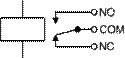
Pneumatic Symbols:
See attached pages, source: http://www.rosscontrols.com/PDFliterature/371c.pdf
Source: http://www1.aucegypt.edu/faculty/gaafar/meng447/Symbols.doc
Web site to visit: http://www1.aucegypt.edu
Author of the text: indicated on the source document of the above text
If you are the author of the text above and you not agree to share your knowledge for teaching, research, scholarship (for fair use as indicated in the United States copyrigh low) please send us an e-mail and we will remove your text quickly. Fair use is a limitation and exception to the exclusive right granted by copyright law to the author of a creative work. In United States copyright law, fair use is a doctrine that permits limited use of copyrighted material without acquiring permission from the rights holders. Examples of fair use include commentary, search engines, criticism, news reporting, research, teaching, library archiving and scholarship. It provides for the legal, unlicensed citation or incorporation of copyrighted material in another author's work under a four-factor balancing test. (source: http://en.wikipedia.org/wiki/Fair_use)
The information of medicine and health contained in the site are of a general nature and purpose which is purely informative and for this reason may not replace in any case, the council of a doctor or a qualified entity legally to the profession.
The texts are the property of their respective authors and we thank them for giving us the opportunity to share for free to students, teachers and users of the Web their texts will used only for illustrative educational and scientific purposes only.
All the information in our site are given for nonprofit educational purposes