
Mechanised cutting produces a superior finish to manual operation.
A variety of mechanised traversing systems are available or the torch can be moved along a straight line or by hand to produce a complex shape.

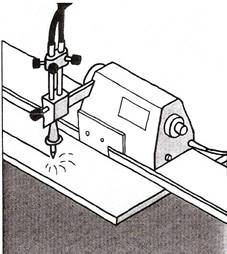
Figure 1 - Operating Techniques
Mechanised systems can be used to prepare the edges of plate prior to welding.
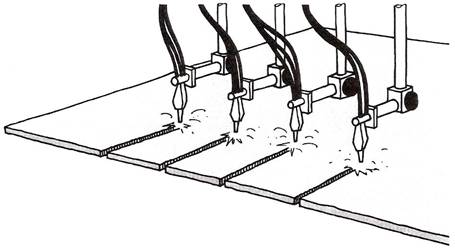
Figure 2 - Mechanised System
More than one cut can be made at the same time.
All operators and users of gases in cylinders must fully understand the potential hazards and properties of the gases they are using and are stored on site.
Each gas has its own characteristics, which affect its behaviour. Gases also change characteristics when subjected to external pressures.
An important characteristic of a gas is its density relative to air because this will determine whether it rises or falls if it leaks. The table below gives the densities of some common gases.
Most gases are colourless and odourless in their natural state so there is little or no warning of a leak. Most fuel gases have or are given a "smell" to aid leak detection.
All suppliers have a complete range of material safety data sheets which detail the chemical and physical properties of the gases as well as their characteristics. In addition suppliers can provide advice on safe handling, storage, transport and use of the product.
IMPORTANT:
Know ALL the properties of the gases you deal with!
This publication outlines the basic properties and characteristics of commonly used industrial gases. We strongly advise you to supplement this information with appropriate material safety data sheets.
Gas density compared to air (approximately) |
Hydrogen 0.06 |
Helium 0.1 |
Nitrogen 0.9 |
Acetylene 0.9 |
Air 1 |
Oxygen 1.1 |
Argon 1.4 |
Carbon dioxide 1.5 |
Propane 1.5 |
Industrial gases are categorised as follows:
Oxidants |
These do not themselves burn but support combustion. By increasing the amount and type of oxidant many things will burn that are not normally flammable. |
Inerts |
These do not generally react with other materials, they do not support combustion nor do they support life. Inert gases should be regarded as asphyxiants because if they leak they displace air and hence the oxygen in the atmosphere. |
Flammables |
These gases when mixed with an oxidant and provided with the right ignition source will burn. An increase in the temperature of the fuel/oxidant mix can also cause ignition. |
Toxics |
These have the potential to cause injury or threaten life, even in small concentrations. |
Corrosives |
These react chemically with other materials causing reactions and deterioration. Toxic gases may be given off. |
Pyrophorics |
Will ignite spontaneously in contact with air. |
A typical gas cylinder is about 1.6m (5 ft.) tall, 200mm (8 inch) diameter base and weighs over 69kg (150 lbs). If it falls, anyone in its way will get hurt.
The dimensions of cylinders vary according to their contents. Free-standing cylinders should be regarded as unstable!
The correct way to move cylinders is with the cylinder:
REMEMBER! Never attempt to catch a falling cylinder - get out of the way!
Anyone moving cylinders should always wear protective footwear, clean gloves and eye protection.
It is obviously better to move cylinders using mechanical aids, for example a trolley or on a cylinder pallet with a forklift truck. The Manual Handling Operations Regulations 1992 require that wherever possible operations are mechanised or handling aids provided.
Where this is not reasonably practicable then assess the handling task, including:
REMEMBER:
A cylinder is never empty.
The correct way to move cylinders over long distances or uneven ground is with the aid of a purpose designed trolley complete with some means of retaining the cylinders.
Cylinders must never be left free standing, they must always be secured or under somebody's direct control. Be aware of the hazards of manually lifting cylinders from horizontal to vertical. Make sure all personnel have attended a specific manual handling course.
Cylinders must never be rolled along the ground as damage may occur to the identification of the cylinder and to the cylinder valve. It can be extremely dangerous to roll steel cylinders full of gas across concrete.
Never transport cylinders with the pressure regulator and equipment attached. Cylinders must not be moved with the valve open.
When faced with an industrial gas cylinder full of gas and asked, "What makes the cylinder potentially hazardous?” the average person is likely to mention:
Most people would not think to add:
But the pressure of the gas in the cylinder is potentially the greatest hazard of those listed above (with the exception of some special gases).
Many gases are considered harmless at normal atmospheric pressure and temperature. However, if they are subjected to high pressure or temperature changes they are potentially hazardous.
A good example is air; it is perfectly safe until pressurised, when its stored energy can make it hazardous.
Cylinders used for storing gases under pressure are designed and built to a high specification and are subjected to regular pressure tests.
The supplier of the gas in the cylinder has a legal duty under the Pressure Systems and Transportable Gas Containers Regulations 1989 to inspect and test the cylinder regularly.
How often the cylinder needs to be tested will depend on:
Always ensure cylinders are upright and secure.
The supplier can establish when the cylinder is due for test from stampings on the neck of the cylinder and by using shaped and coloured "test rings" fitted around the neck of the cylinder. Each colour and shape of test ring will determine in which year the test is to be carried out. This test ring is for the suppliers use and need not concern the user of the cylinder.
Cylinders are filled to different pressures dependent on the characteristics of the gas and the capability of the cylinder. They are made of steel or aluminium alloys. All cylinders are manufactured to meet European and British Standards and/or Home Office Specifications.
Although some cylinders are welded most are solid drawn from a single steel billet. This gives them strength and robustness. In addition some cylinders have a bursting disc to vent the gas quickly and reduce pressure should the cylinder be subjected to heat for example.
Most cylinders do not have a bursting disc. If the pressure increases abnormally, the cylinder normally splits or peels open to release its contents rather than fragmenting. However, it does depend on circumstances and the reasons for failure.
There are various British Compressed Gases Association (BCGA) Codes of Practice and Health and Safety Executive (HSE) guidelines for the storage of different gases. For industrial gases refer to BCGA Guidance Note GN2 which provides guidance on the hazards of storing gas cylinders and good practice for the controlling of risks.
Every storage situation should be considered on its merits therefore risk assessments should be carried out for each storage location. The following notes may be used as a basic guide; however special circumstances may necessitate variations on these recommendations.
In the event of an incident the fire brigade will arrive on site and expect to receive information from the site fire marshal (safety officer etc.) on the type and number of cylinders as well as their location. If this information is not available no-one may enter the premises.
You must set emergency procedures for each storage location. For large storage areas, consult the emergency services.
There are a number of issues to be considered when storing cylinders:
Personnel must be trained in the safe handling and storage of gases and satisfy their employer that they have understood the training and are capable of taking the appropriate action in the event of an emergency.
This should include:
Training should be formalised and recorded with refresher courses as appropriate.
Ensure ease of access into and around the storage facility. The provision of aisles of at least 0.6m wide is important to avoid the 'domino' effect. In addition:
The best storage facility available is of little use if the store person does not control what goes where. Good housekeeping is essential:
REMEMBER:
Know ALL the properties of the gases you deal with!
The location of the store is vital:
REMEMBER:
A cylinder is never empty.

Figure 3 - Portable Oxy-Acetylene Welding and Cutting Equipment Assembly
Acetylene is composed of Hydrogen and Carbon, as are most fuel gases. It is mainly the carbon which provides the intense heat and very high flame temperature (3100°C) when burned with oxygen. If sufficient oxygen is not provided, then the carbon is given off into the air as black, sooty smuts.
Acetylene has a very high proportion of carbon in it and if the oxygen is turned down to provide a flame with excess carbon, the carbon is taken into the steel to provide a high carbon surface, used for hard surfacing operations.
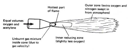
Figure 4 - Oxy-Acetylene Flame Showing the Various Zones
A neutral oxy-acetylene flame burns equal proportions of oxygen and acetylene and is reducing in nature, thereby reducing any iron oxide to iron and taking up the oxygen; consequently there is no need to use a flux when welding steel. It should be noted that iron oxide is not refractory.
AIM To demonstrate the three oxy-acetylene flame settings.
EQUIPMENT Oxy-acetylene welding equipment, including goggles and flint lighter.
THEORY There are three distinct flame settings:

Figure 5 - Neutral Flame
Cone Tip Hottest Part Approx. 3100°C

Figure 6 - Carburising Flame

Figure 7 - Oxidising Flame
During many manufacturing processes it is often necessary to cut metals to size or to shape their edges with a bevel ready for welding. This chapter describes the various processes that can be employed for this purpose.
There are two operations involved in oxy-fuel cutting.
Heating flames are directed on to the metal to be cut, until it is raised to a bright red heat. This is called the ignition temperature, about 900°C.
A stream of high-pressure oxygen is directed on to the hot metal. This immediately oxidises the metal and, as the melting point of this oxide is below the melting point of steel, the oxide is melted and blown away.
The metal is therefore cut by a chemical action; the iron or steel is not melted. The heat needed to keep the cut going is provided partly by the heating jets and partly by the chemical action.
|
Good cut. |
|
Cutting speed too fast. |
|
Cutting speed too slow. |
|
Nozzle too high. |
|
Irregular cutting speed. |
|
Preheating flame too high. |
|
Preheating flame too low. |
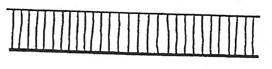
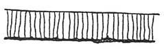
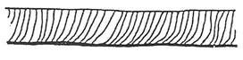
Table 1 - Examination of Flame-Cut Edges

Figure 9 - Some tips for achieving a good cut
Blowpipes are usually of the injector type, so that they can be used on both high- and low-pressure systems. The modern type of cutting nozzle has the mixing chamber incorporated in it, so that a 'blowback' usually only goes as far as the nozzle; the high velocity of the gas tends to prevent it from going any further.
The size of the cutting blowpipe varies with the thickness of work; special heavy-duty blowpipes are available. Nozzle sizes also vary to suit different thicknesses of plate.
Cutting machines, in which one or several cutting blowpipes can be employed, are faster and more accurate than hand cutting.
Because cutting is essentially an oxidising process, little or no steel is melted. The kerf (the width of cut) should therefore be quite clean, and the top and bottom edges should be square. On examining melted oxides after cutting, it has been found that they contain up to 30 per cent unmelted steel, which has been scoured from the sides of the cut by the high-pressure oxygen stream. This scouring can be seen if the sides of the kerf are inspected, because drag lines will be faintly etched on the faces of the metal. For an incorrect cut, these drag lines will be more pronounced (Figure 8 and Table 1).
Figure 9 shows some tips for achieving a good cut.
It takes a fair amount of skill to maintain a constant rate of travel over the work (Figure 10). The general quality of cut produced with a hand-held cutting torch is therefore usually inferior to the quality of cut made with a correctly adjusted cutting machine.
Cutting guides can help to keep the torch on the correct line of cut. A roller attachment can be used to maintain the correct nozzle-to-work distance.
Stack cutting can be used to cut more than one plate at once, if the same shape is required (Figure 11).
Modern cutting machines are capable of making high-quality cuts within close limits. Many machines prepare bevelled edges for welding without any additional dressing operations being required.
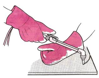
Figure 10 - Oxy-fuel Gas Cutting Freehand
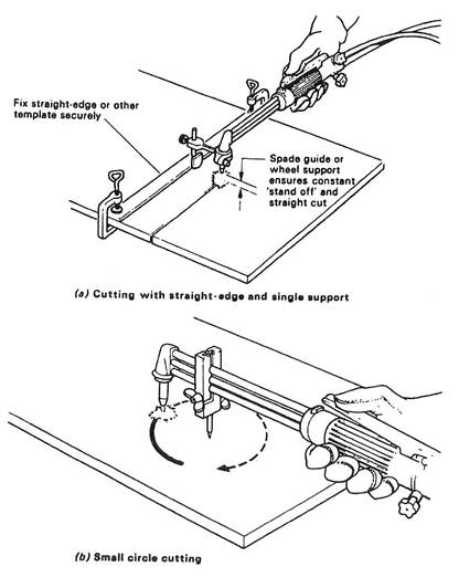
This can be made much easier by the use of guides and attachments (see Figure 11).
There are many different designs of cutting machine. Some machines have a single cutting torch, while others have many. One design moves the cutting torch or torches above the plate to be cut, while another design keeps the cutting head stationary and moves the work beneath it.
The simplest cutting machine is the straight-line type, which consists of a carriage, mounted on a track, containing the cutting torch. The carriage is traversed over the work by a variable-speed electric motor (Figure 12).

Figure 11 - Stack Cutting
It is possible to cut a stack of plates if they are clamped tightly together.
Cut a small circle using a small circle guide. Maintain the pivot point in the centre punch mark.
Other machines, often called profiling machines, can guide the cutting head or heads by following a template. Some guiding systems have a magnetic wheel device that will follow the outline of a steel template, while others contain a photo-electric cell that will follow the black outline of a drawing.
Figure 12 - Typical Straight-Line and Circle-Cutting Machine

Figure 13 - Flame-cutting Procedure
A Pre-heat to ignition temperature
B Move the cutting torch backwards, just clear of edge
C Open the cutting oxygen valve
D Commence cutting
E Continue cutting
Table 2 - Approximate Pressures for Hand Cutting Steel Plate
Note:
The above figures are given only as a guide since the actual requirements may vary according to the nature of the work.
Some pressure regulators are fitted with gauges which are calibrated in kg/cm². 1 kg/cm² is approximately equal to 1 bar.
The cutting torch nozzles are so designed that they have a central port around which is either an annulus or several smaller ports. The smaller ports are circular holes in the case of acetylene cutting nozzles, and take the form of annular slots for propane. Through the smaller ports is fed the fuel gas mixed with the correct proportion of oxygen for the purpose of pre-heating the metal. The central port of orifice through which the main jet of oxygen is released will vary in diameter according to the size of the cutting nozzle required. The orifice diameter is increased as the thickness of the plate to be cut is increased – in general, a particular size of nozzle is used to cut a small range of thicknesses.
Figure 14 gives details of typical cutting nozzles.
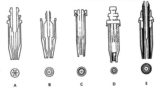
Figure 14 - Cutting Nozzle Design Feature
A One-piece ACETYLENE cutting nozzle – parallel bore, 3-9 pre-heat holes, no skirt.
B Two-piece ACETYLENE cutting nozzle – venturi bore, pre-heat annulus, no skirt.
C Two-piece NATURAL GAS nozzle-venturi bore, pre-heat flutes, long skirt.
D Two-piece PROPANE nozzle – parallel bore, pre-heat slots, long skirt.
E Two-piece PROPANE nozzle – parallel bore, pre-heat flutes, long skirt, oxygen curtain.
 Basically there are three types of devices which may be used for radial cuts and circle cutting.
 Special cutting device for small holes
This is provided with vertical adjustment to obtain correct nozzle to plate distance. The support rides on the plate to be cut and may be pressed against a straight edge.
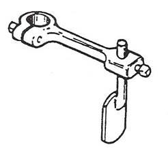
Figure 15 - Spade Guide
Small circles may be cut by clamping a pivot on to the gas tubes of the blowpipe.

Figure 16 - Small Circle Guide
Used for large circles. It is fitted with a wheel support and an adjustable pivot.
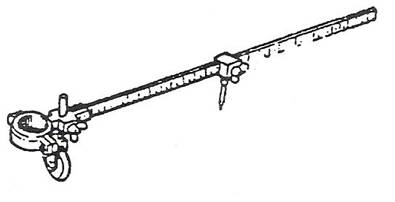
Figure 17 - Radius Bar
Bevel cutting may be obtained by either setting the wheels of the double support at different levels or by using the slotted clamping attachments.

Figure 18 - Bevel Guide
Assemble the equipment and arrange the material to be cut in a convenient position; faster cutting and a smoother finish is possible if rust and scale are removed from the path of the cut. Light up the nozzle and hold the blowpipe with the nozzle at right angles to the plate and apply the heating name to the edge of the material furthest from the operator. A spade or roller guide attached to the nozzle is of assistance in holding the blowpipe steady, so increasing the speed of cutting.
When the edge of the metal attains a bright red heat, operate the cutting oxygen lever and draw the blowpipe towards the operator's body along the line of cut at a speed recommended in the data tables.
The above remarks apply to cutting mild steel plate of normal thicknesses. The following points should be noted for differing cutting requirements.
Figure 19 - Cutting Techniques
Because of the heavy gas consumption when cutting thick material, ensure that there is "an adequate supply of fuel gas and use a battery of oxygen cylinders coupled together or pipeline supplies. On very thick material, heat metal to bright red heat, operate the cutting lever, wait until the cutting reaction is seen to be right through the metal thickness to the bottom edge, and then draw the blowpipe along.
Clean the surface before starting to cut. It is often an advantage to incline the tip of the nozzle a little to help to undercut paint or scale. Unless ventilation is very good fume extraction should be installed at the point of cutting. In some cases it may be necessary to use a respirator as well.
Of all the methods used for material removal in the fabrication industry, the flame-cutting process plays a prominent part in the preparation of mild-steel plate material for welded fabrications. It is readily applicable to very large thicknesses of material and allows a multiplicity of shapes or contours to be cut - two points which restrict the use of guillotines.
It is faster than machining operations, which is an important advantage in connection with plate edge preparations for welded joints.
Most metals oxidise. The rate of oxidation in air depends upon the type of material and the temperature. The properties of the oxides formed are different from that of the parent metal.
Oxygen combining with a metal at a slow rate, as in the case of the rusting of iron, is referred to as 'OXIDATION', whereas if the formation of the oxide is very rapid, it is referred to as 'COMBUSTION' or 'BURNING'.
Generally, a rise in temperature of the metal has the effect of accelerating the rate of oxidation. In the case of mild steel when heated at a temperature of 890°C (bright cherry red), complete combustion takes place if it is in any atmosphere of pure oxygen, and a magnetic oxide of iron is formed.
Flame cutting is made possible by the fact that:
The process consists of creating a local hot spot on the surface of the steel with a flame to ignition temperature and directing a high pressure jet of pure oxygen on to this PRE-HEATED spot. A vigorous and rapid chemical reaction takes place, the steel burns and oxides are formed. The exothermic reaction produces a great deal more heat. This heat is sufficient to melt the oxides formed on the metal.
Figure 20 - The Action of Oxygen Cutting
Allow 1 – 2 mm for the “kerf”.
The PRE-HEATING FLAME has a specific function:
To transmit sufficient heat to the surface of the steel to compensate for the heat loss due to thermal conductivity.
In this respect ACETYLENE, because of its high flame temperature, has the following advantages over PROPANE and Natural Gas.
The disadvantage of the high-temperature acetylene preheat flame is the tendency for excessive melting of the top edges of the cut.
This is generally associated with the use of too large a pre-heating flame once the cut has started, and this problem may be eliminated by correct flame control and distance from the workpiece.
The pre-heating flame must be of sufficient intensity in order to break up surface scale and to maintain the steel at ignition temperature irrespective of surface irregularities.
Only those materials whose combustion or ignition temperature is below their melting point can be flame cut. Otherwise the material would melt away before OXIDATION could take place, making it impossible to obtain a cleanly cut edge.
NON-FERROUS METALS CANNOT NORMALLY BE FLAME CUT. Cast iron and stainless steel require special procedures and even then a 'flame-cut edge' of the same quality as with plain carbon steel is difficult to obtain.
 Sharp top edge.
Almost vertical lines.
Square face with light slag.
Good bottom edge.
 Melted and rounded top edge.
Lower part of cut face gorged irregularly.
Bottom edge rough.
Heavy scale on cut face.
Heavy dross on underside difficult to remove.
Top edge not sharp and may be undercut.
 Drag lines very marked and uneven sloping backwards.
Irregular cut edge.
Source: http://local.ecollege.ie/Content/APPRENTICE/liu/metalfab_notes/module_2/Introduction%20to%20the%20Oxy-Fuel%20Cutting,%20Freehand-Attachments_M2_U1.doc
Web site to visit: http://local.ecollege.ie
Author of the text: indicated on the source document of the above text
If you are the author of the text above and you not agree to share your knowledge for teaching, research, scholarship (for fair use as indicated in the United States copyrigh low) please send us an e-mail and we will remove your text quickly. Fair use is a limitation and exception to the exclusive right granted by copyright law to the author of a creative work. In United States copyright law, fair use is a doctrine that permits limited use of copyrighted material without acquiring permission from the rights holders. Examples of fair use include commentary, search engines, criticism, news reporting, research, teaching, library archiving and scholarship. It provides for the legal, unlicensed citation or incorporation of copyrighted material in another author's work under a four-factor balancing test. (source: http://en.wikipedia.org/wiki/Fair_use)
The information of medicine and health contained in the site are of a general nature and purpose which is purely informative and for this reason may not replace in any case, the council of a doctor or a qualified entity legally to the profession.
The texts are the property of their respective authors and we thank them for giving us the opportunity to share for free to students, teachers and users of the Web their texts will used only for illustrative educational and scientific purposes only.
All the information in our site are given for nonprofit educational purposes