
When forming the following exercises we may use a folding machine or simply a vise.
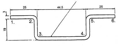
Figure 1 - Forming Technique ‘A’
If we use the folders we should allow for the 3mm metal thickness when setting the swing beam (Figure 2). Bend at 2 and 5 first and then 3 and 4, which are bent in the opposite direction to 2 and 5.
Figure 2 – Forming Technique ‘B’
To arrive at the blank size for Figure 1 we do the following:
Distance from 1 – 2 = 25 – 3 = 22 mm (22mm is also first bending distance)
Distance from 5 – 6 = 25 – 3 = 22 mm (22mm + 16mm is second distance)
Distance from 2 – 3 = 19 – 3 = 16 mm (i.e. bend distance 3 and 4)
Distance from 4 – 5 = 19 – 3 = 16 mm
Distance from 3 - 4 = 44.5 mm
120.5mm = total blank size
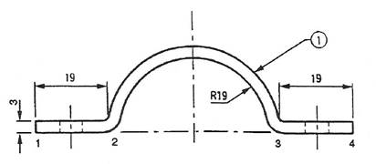
Figure 3 - Forming Technique 'C'
Blank size for C = 19 + 9 +½
Circumference – 2 M.T.
The 2 M.T. (metal thickness) is a close approximation only and it may be necessary to make a second attempt in making the above bracket.
To fabricate bracket bend at 2 and 3 90º bends. Grip metal with vise grips and shape over a suitable round bar. The diameter of the bar should be slightly smaller than the bracket diameter.
19 + 19 + ½ π D – 2 M.T. (3)
38 + 59.7 – 2 M.T.
38 + 59.7 – 2 (3)
97.7 – 6
91.7 mm is size required
For large holes, say 9 mm or more it is good practice to drill a pilot hole. It is especially useful on hard materials such as stainless steel. (Apply medium pressure drilling stainless).
For some purposes punching instead of drilling may be used. Punching is cold working and may cause minor cracks to appear around the hole. Hence drilling is better but more time consuming.
Accuracy is important to get holes into proper alignment. Work pieces should be held securely while drilling. Future bends and material thickness may need to be considered in some jobs.
The tang is provided for the purpose of filling the file into a wooden handle. For safety reasons, files should always be fitted with suitable file handles. The point, body and shoulder are hardened and tempered, whilst the tang is usually left in the softened condition to prevent it from inadvertently 'snapping off'.
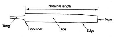
Figure 4 - The Engineer's File
The file plays a very important part in material removal, and filing operations range from 'roughing down' to final finishing on flat and curved surfaces. The main features of a file are shown in Figure 4. The specifications for files are determined by length, grade of cut and shape. The grade or cut of a file depends upon its length: the shorter the file, the smaller will be the pitch of its teeth.
Table 1 shows the pitch range and applications of normal available files.
There is a very wide variety of files available for engineering purposes; the type or shape selected is generally governed by a particular application. Figure 7 shows a range of files and typical uses.

Figure 5 - File Teeth
The file tooth, just like any other cutting tool, must have correctly applied tool angles, as shown in Figure 5.
The single cut file has a series of parallel teeth formed at an angle of about 70° to the axis of the file.
The double cut file has a second series of parallel teeth formed in the opposite direction and crossing the others at an angle of about 45° and is usually made by over-cutting the single-cut file, as shown in Figure 5. The double-cut file offers a number of individual cutting teeth as opposed to a long single tooth across the width of the file, as is the case with the single-cut file. Since the filing effort is less than that required for a single-cut file, heavy duty files are usually made with double-cut teeth.
In order to generate a plane surface by filing, the file must be moved parallel to the plane of the required surface. This carefully controlled movement depends solely on the muscular co-ordination of the operator which involves certain essential basic principles.
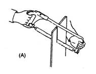
For correct control, the top of the vice jaws should be level with the forearm held parallel to the ground.
The file can only be controlled when the body is correctly balanced. Figure 6 illustrates how the feet should be placed relative to the vice to achieve this.
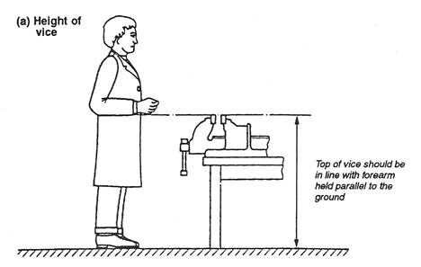
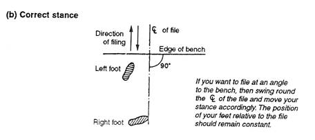
Figure 6 - Use of the File
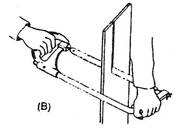
An important point to remember when filing metal parts is that most, if not all, files are designed to cut on the forward direction. Therefore filing pressure should be given only when the file is pushed away from the operator and released when the file is returned for the next forward movement. When using a flat file, one hand applies the pressure whilst the other provides the surface movement of the file. Wherever possible, commence with the point of the file and move the file forward so as to finish with the shoulder portion. Using the whole length of the file prevents local wear. It also ensures a quicker and more efficient cutting action. The method of filing a flat surface or the edge of a metal strip is shown in Figure 7.
The fingertips play an important part in keeping the file straight during the filing of a flat surface. Care must be exercised not to 'rock' the file during the forward movement; otherwise a convex, rather than the required flat surface, will be generated. Figure 7 shows how the file should be held for various operations.

Figure 7 - Correct Grip
Care must be taken to ensure 'flatness' of filing. Frequent inspection of the work, during the filing operation, using a straight edge or a surface table, will check for any unevenness in this respect. When using round or half-round files, it is good practice to give a certain amount of rotational action about their axes whilst moving them back and forth. This action produces a smoother and more regular concave surface than when they are merely moved in a fore-and-aft direction. Remember that during each stroke of the file, the weight must be gradually transferred from the front hand to the back hand.
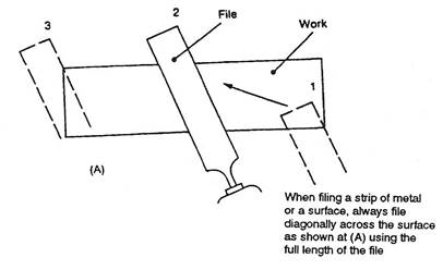
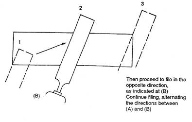
Figure 8 - Correct Filing Method
As draw filing is employed for finishing, the teeth of the file must be free from adhering metal particles, otherwise scratches will occur on the metal's surface. Regular use of the file card, in order to clear the teeth, is necessary during draw filing. For final finishing it is advisable to rub over the teeth of the file with a block of chalk, so as to fill the spaces between the teeth. This not only prevents scratching, but also gives a smoother finish than would otherwise be the case.
Grade |
Pitch (mm) |
Use |
Rough |
1.8 – 1.3 |
Soft metals and plastics |
Bastard |
1.6 – 0.65 |
General roughing out |
Second Cut |
1.4 – 0.60 |
Roughing out tough materials |
Smooth |
0.8 – 0.45 |
General finishing and draw filing |
Dead Smooth |
0.5 – 0.25 |
Not often used except on tough die steels where high accuracy and finish is required |
Table 1 - File Grades
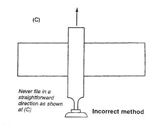
Figure 9 - Incorrect Filing Method

Figure 10 - Sections and Uses of Files
Figure 11 shows a typical hacksaw with an adjustable frame that will accept a range of blade sizes. For optimum results, the blade should be carefully selected for the work in hand; it must be correctly fitted, tensioned and correctly used.
Like the file, the hacksaw blade cuts only in the forward direction. Steady, forward strokes should be applied, utilising the whole length of the blade, whilst exerting sufficient pressure to prevent the blade sliding. Avoid using short fast strokes which draw the temper from the teeth of the blade causing rapid local wear. Never change a blade part way through a cut. The greater 'set' of the new blade will cause it to jam in the slot already cut and break. If a change of blade is unavoidable, start a new cut to the side of the old one.

Figure 11 - Hacksaw with Adjustable Frame
 The hacksaw blade is held tightly in the frame by means of a tensioning screw and wing nut fitted to one end. A pin hole each end of the blade is located on the pins provided - one on the tensioning device, the other on the fixed part of the frame. The adjustable and fixed members of the frame which carry the locating pins are made of square section permitting them to be housed in the frame in one of two positions:
 The normal position which enables the blade to be fitted parallel with the frame;
With the blade fitted in the normal position, the depth or length of cut is restricted by the frame, as shown in A and B above. With the blade fitted in the 90° position the frame does not obstruct when making long cuts, or when cutting deep sections and similar parts.
Material |
Pitch (mm) |
Pitch (mm) |
Ferrous metal |
1.4 – 1.6 |
0.8 |
Non-ferrous metal |
1.8 – 2.1 |
10.0 – 1.2 |
Table 2 - Pitch of Metal
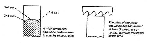
Figure 12 - Hacksaw Filing
When using the hacksaw the correct stance is the same as for filing. Saw at about 60 strokes per minute for H.S.S. blades or 50 strokes per minute for low tungsten blades.
Where possible the angle of the blade to the cut should be approximately 30°.
A hacksaw blade is classified by the pitch of its teeth, length of the blade and the material of which it is made. Flexible low tungsten blades are hardened at the cutting edge, whilst high speed blades are hardened throughout. High speed blades are the strongest and best blades for cutting hard metals. There are different types of saw teeth for cutting various kinds of metal, as shown in Table 3.
Type |
Pitch (mm) |
Remarks |
Coarse pitch |
1.8 – 2.2 |
The most satisfactory blade for mild steel, since the coarse pitch provides proper clearance between the teeth to enable the chips to twist and curl naturally. If fine teeth were used they would become clogged with chips and may jam and break. The coarser the blade, the better for cutting cast iron. |
Medium pitch |
1.4 – 1.6 |
These are general purpose blades used principally for cutting hard brass, and medium and hard steels such as tool steels, since the hard chips are small and do not require much clearance. |
Fine pitch |
0.8 – 1.3 |
Employed chiefly for cutting light sections. A coarse pitch spans the thickness of the material and, in such cases, results in broken teeth. Used for cutting angle iron, copper tubing, iron pipe and very hard steels. |
Table 3 - Types of Saw Teeth
Source: http://local.ecollege.ie/Content/APPRENTICE/liu/sheetmetal_notes/Filing,%20Drilling,%20Forming_M1_U6.doc
Web site to visit: http://local.ecollege.ie
Author of the text: indicated on the source document of the above text
If you are the author of the text above and you not agree to share your knowledge for teaching, research, scholarship (for fair use as indicated in the United States copyrigh low) please send us an e-mail and we will remove your text quickly. Fair use is a limitation and exception to the exclusive right granted by copyright law to the author of a creative work. In United States copyright law, fair use is a doctrine that permits limited use of copyrighted material without acquiring permission from the rights holders. Examples of fair use include commentary, search engines, criticism, news reporting, research, teaching, library archiving and scholarship. It provides for the legal, unlicensed citation or incorporation of copyrighted material in another author's work under a four-factor balancing test. (source: http://en.wikipedia.org/wiki/Fair_use)
The information of medicine and health contained in the site are of a general nature and purpose which is purely informative and for this reason may not replace in any case, the council of a doctor or a qualified entity legally to the profession.
The texts are the property of their respective authors and we thank them for giving us the opportunity to share for free to students, teachers and users of the Web their texts will used only for illustrative educational and scientific purposes only.
All the information in our site are given for nonprofit educational purposes