
Tolerances treat the uncertainty with which the realized shape or measurements of a real manufactured object compare to their design ideals. If all parts could be manufactured perfectly as designed, there would be no need for tolerancing practices. However, it is certain that this cannot be done for finite cost in any but the most trivial cases. In the drawing world, tolerances are noted on the drawing per standard notations such as ANSI Y14.5 or ISO 1101.
There are two main classes of tolerances, dimensional and geometric. Dimensional tolerances are addressed in “Recommended Practices for Dimensions and Dimensional Tolerances” written by Markus Hauser, Mike Strub and Tom Hendrix, dated April 18, 2000.
Geometric tolerances are the more complex of these two types. Geometric tolerances provide more flexible means for controlling shape than do dimensional tolerances. They achieve this by enabling tolerances to be defined independently of explicit dimensions. This enables tolerances to be specified that are more closely related to the functional requirements of the design, such as strength and fit. These tolerances are the subject of this recommended practices guide.
This document covers the recommended usage and implementation of geometric tolerances defined in Application Integrated Construct (AIC) 519. This AIC is the result of a harmonization effort between AP214 and AP224. This AIC is also the basis for the tolerance modules to be included in AP203 Edition 2.
This document is not intended as a primer on geometric tolerancing. The explanations included are only provided to relate common tolerancing techniques to the STEP entity structures. This is not a comprehensive coverage of any existing draughting standard but does provide a capability to exchange a variety of typical models. Future versions of this document will address additional capabilities.
This document covers the application of tolerances to boundary representation solid models. The application of tolerances to wireframe or other geometric models is not covered here.
The tolerances addressed in this document are:
Angularity
Circular runout
Circularity
Coaxiality
Concentricity
Cylindricity
Flatness
Parallelism
Perpendicularity
Position
Profile of a line
Profile of a surface
Roundness
Straightness
Symmetry
Total runout
Tolerance modifiers (Maximum and minimum material condition, regardless of feature size and projected tolerance zone) are also addressed.
A geometric tolerance describes a constraint on the acceptable deviation of a manufactured object from the ideal design. Tolerances are applied to the geometric features of a part, such as faces and holes.
The fundamental principles of geometric tolerances can be found in national and international standards such as ANSI Y14.5M-1194 or ISO 5459-1981.
There are several subtypes of the geometric_tolerance entity, which are not mutually exclusive. For example, tolerances that reference datums are of type geometric_tolerance_with_datum_reference. Tolerances that include a modifier such as maximum material condition are of type modified_geometric_tolerance. Many typical engineering tolerances combine these. In these cases, complex entities instances will occur in the Part 21 file.
In STEP, the tolerance entities are associated with a shape_aspect that identifies the toleranced feature. In the case of a solid boundary representation model, the feature of the part is represented by a topological_representation_item such as an advanced_face.
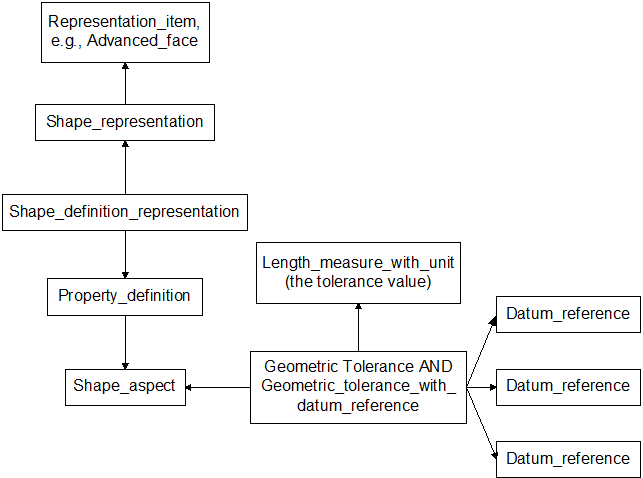
Figure 1 Relating a typical tolerance to a feature
Some types of tolerances refer to one or more datums in order to represent the requirements on the shape. Datum systems are related datums that provide a reference system for describing requirements on the product shape. Datum systems are defined by datum entities and their corresponding datum_feature entities.
A datum is a theoretically exact geometric reference, such as an exact point, axis or plane, to which toleranced features are related. A datum is the origin from which the location or geometric characteristics of features of a part are established. A datum may be based on one or more datum features of a part (Definition from ISO 5459-1981).
Since the datum is intended to be the idealized geometry, unbounded geometric entities are used as the representation_item. For a boundary representation solid model, these entities are planes, lines, etc.
Datum features are tangible features of a part, for example a face that provides a reference system for measurements of the actual part. Datum features must lie on the physical boundary of the shape. Consequentially, datum_feature entities are related to topological entities that represent those boundaries in the solid model such as an advanced_face.
Where tolerances contain references to datums, the tolerance entity is considered a subtype of geometric_tolerance_with_datum_reference. It thus inherits the datum_system attribute, which is the mechanism for pointing to the datum_reference entities.
In the figure below, the tolerance entity, e.g., a positional_tolerance uses three datum_reference entities to describe the datum system for the tolerance. The datum_reference points to a datum entity, which in turns points to a geometric element that represents the datum. The datum_feature, i.e., the feature on the part corresponding to the datum, references the topological element of the solid model representing that feature, i.e., the advanced_face. See Figure 2 for details.

Figure 2 Datums and datum_features
A datum_target designates a specific point, line or area of contact on a part that is used in establishing a data reference frame (definition from ANSI Y14.5). It differs from a datum_feature in that it identifies a restricted region of a feature, i.e. a point, line or area of a surface rather than a topological feature. Typically, two or more datum_target elements are used to define a datum
A datum_target is represented by a placed_datum_target_feature. The placed_datum_target_feature is related to datum that it helps establish via the mechanism depicted in Figure 3 below. The point, line or area of the datum_target is represented by a shape_representation_with_parameters containing a measure_representation. See Figure 3.

Figure 3 Datum targets
A reference to a datum can contain a modifier that specifies a condition, such as maximum material condition. For example, a control frame whose visual representation is depicted in Figure 4 is represented in a similar manner to an unmodified datum reference except that instead of a datum_reference, the subtype referenced_modified_datum is used. The modifier attribute contains the condition information as a value of type limit_condition.

Figure 4 Modified datum reference
Certain engineering tolerances are modified by adding conditions. The conditions identified in STEP are defined in the limit_condition enumerated type. The values defined are: maximum_material_condition, least_material_condition and regardless_of_feature_size. These are referred to in tolerance standards as MMC, LMC and RFS respectively.
When the tolerance is modified, the tolerance entity is considered a subtype of modified_geometric_tolerance and thus inherits the modifier attribute. The modifier attribute contains the enumerated value of type condition. The general structure is depicted in Figure 5.
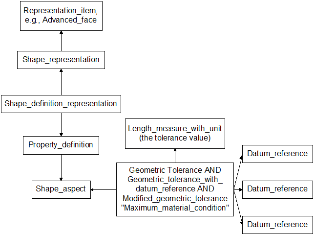
Figure 5 Modified Tolerance
In some cases, a tolerance is applied to more than one feature of the part. Examples include a tolerance applied to a pattern of holes or a tolerance applied to two parallel faces of a part. In these cases, a composite_shape_aspect is used to relate the various features together and the tolerance is applied to the composite_shape_aspect. See Figure 6 for details.
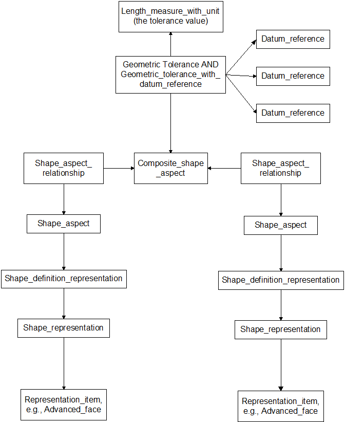
Figure 6 Tolerancing multiple features
Some tolerances have multiple requirements as represented by a multiple frame tolerance control frame who visual representation is shown in Figure 7.
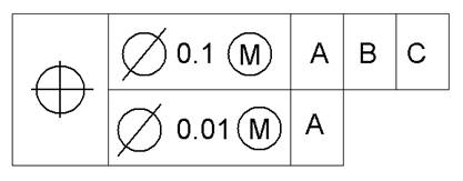
Figure 7 Composite Control Frame
This is implemented by creating the appropriate geometric_tolerance entity for each frame. The geometric_tolerance entities are then related via a geometric_tolerance_relationship. The description attribute of the geometric_tolerance_relationship entity shall contain the value “Composite Tolerance”. See Figure 8 for the structure of the tolerance depicted in Figure 7.
In the geometric_tolerance_relationship entity, the upper frame is the “relating” reference and the lower frame is the “related” reference. For tolerances with more than two frames, multiple geometric_tolerance_relationship entities are used to relate the frames together. For example, a tolerance with three frames would require two geometric_tolerance_relationship entities: one relating the top (“relating”) and middle frames (“related”), the second relating the middle (“relating”) and the bottom (“related”) frames. These relationships will allow the receiver to reconstruct the semantic relationships as well as the visual representation.

Figure 8 Structure of Composite Tolerance
Consider an example of a location tolerance on a hole whose visual representation as a control frame is:

Interpreting this in STEP (reading the control frame left to right) the location tolerance is a position_tolerance, locating a cylindrical feature, with a tolerance value of 0.1, with a modifier condition of maximum material condition, referencing datums A, B and C in that order.
Using the AIC 519 schema, this would be a complex entity instance comprising a
geometric_tolerance AND
position_tolerance AND
modified_geometric_tolerance AND
geometric_tolerance_with_datum_reference
In the Part 21 file, this would appear as:
#1000=(GEOMETRIC_TOLERANCE (‘position’, ‘Positional tolerance for hole 1’, 1045, #1008)
GEOMETRIC_TOLERANCE_WITH_DATUM_REFERENCE ((#1002, #1003, #1004))
MODIFIED_GEOMETRIC_TOLERANCE (.MAXIMUM_MATERIAL_CONDITION.)
POSITIONAL_TOLERANCE ());
The datum references A, B and C would be referenced by:
#1002=DATUM_REFERENCE(1,#1005);
#1003=DATUM_REFERENCE(2,#1006);
#1004=DATUM_REFERENCE(3,#1007);
The DATUM entities are defined and related to the model geometry via:
#1005=DATUM('Datum A','Datum A',#40,.F.,'A');
#1058=PROPERTY_DEFINITION('Datum geometry','Geometric plane of datum',#1005);
#1059=SHAPE_DEFINITION_REPRESENTATION(#1058,#1061) ;
#1061=SHAPE_REPRESENTATION('Representation of datum plane',(#98),#49) ;
#1006=DATUM('Datum B','Datum B',#40,.F.,'B');
#1068=PROPERTY_DEFINITION('Datum geometry','Geometric plane of datum',#1006);
#1069=SHAPE_DEFINITION_REPRESENTATION(#1068,#1071) ;
#1071=SHAPE_REPRESENTATION('Representation of datum plane',(#214),#49) ;
#1007=DATUM('Datum C','Datum C',#40,.F.,'C');
#1078=PROPERTY_DEFINITION('Datum geometry','Geometric plane of datum',#1007);
#1079=SHAPE_DEFINITION_REPRESENTATION(#1078,#1081) ;
#1081=SHAPE_REPRESENTATION('Representation of datum plane',(#190),#49) ;
where #98, #214 and #190 are the plane entities representing the datum planes in the B-rep solid model.
This section contains the recommendation on population of the values for the tolerance entities.
Since the geometric_tolerance entity is the supertype for the tolerance entities, most of the attributes are inherited from it. The recommended values for the geometric_tolerance entity are:
Name |
Explanation |
Geometric_tolerance |
|
name |
One of the following strings: |
description |
No requirement defined – instantiate this attribute with an empty string. |
magnitude |
The measure_with_unit that contains the tolerance value.. |
toleranced_shape_aspect |
The shape_aspect the tolerance is associated to. The type of shape_aspect varies depending on the type of tolerance. |
The tolerance is related to the shape_aspect referencing the advanced_face whose underlying geometry is planar that is being toleranced to the datum.
The tolerance is related to the shape_aspect referencing the advanced_face whose underlying geometry is the cylindrical_surface that is being toleranced.
See Roundness, Section 5.13
This is the ISO term for concentricity. See 5.5.
The tolerance is related to the shape_aspect referencing the advanced_face whose underlying geometry is the cylindrical_surface that is being toleranced.
The tolerance is related to the shape_aspect referencing the advanced_face whose underlying geometry is the cylindrical_surface that is being toleranced.
The tolerance is related to the shape_aspect referencing the advanced_face whose underlying geometry is planar that is being toleranced to the datum.
The tolerance is related to the shape_aspect referencing the advanced_face whose underlying geometry is planar that is being toleranced to the datum.
The tolerance is related to the shape_aspect referencing the advanced_face whose underlying geometry is planar that is being toleranced to the datum.
Position tolerances can be applied to several types of features. When the feature is a hole, the tolerance is related to the shape_aspect referencing the advanced_face whose underlying geometry is the cylindrical_surface that is being toleranced. For other features, such as tabs, the tolerance is related to the composite_shape_aspect that defines the feature.
The tolerance is applied to a shape_aspect that is related to another shape_aspect containing a plane or an intersection_curve. The two shape_aspect entities are related via a shape_aspect_relationship whose name attribute is ’affected plane association’, when the related shape-aspect corresponds to the reference plane, or ’resulting intersection curve association’, when the related shape-aspect corresponds to one of the intersection curves.
The tolerance is applied to a shape_aspect that references an advanced_face whose underlying geometry is planar that is being toleranced.
The tolerance is related to the shape_aspect referencing the advanced_face whose underlying geometry is the cylindrical_surface that is being toleranced. Roundness is the ISO term for what ASME Y14.5 refers to as circularity.
The tolerance is applied to a shape_aspect that references an advanced_face whose underlying geometry is planar that is being toleranced.
Where the tolerance is applied to a cylinder, the tolerance entity is related to a shape_aspect referencing the advanced_face whose underlying geometry is the cylindrical_surface. Where the tolerance is applied to opposing faces, the tolerance entity is related to a shape_aspect referencing the advanced_faces whose underlying geometry are the opposing planar faces.
The tolerance is applied to a shape_aspect that references an advanced_face whose underlying geometry is the surface that is being toleranced. The surface may be cylindrical or planar.
ENTITY angularity_tolerance
SUBTYPE OF (geometric_tolerance_with_datum_reference);
WHERE
WR1: SIZEOF (SELF\geometric_tolerance_with_datum_reference.datum_system) < 3;
END_ENTITY;
ENTITY circular_runout_tolerance
SUBTYPE OF (geometric_tolerance_with_datum_reference);
WHERE
WR1: SIZEOF (SELF\geometric_tolerance_with_datum_reference.datum_system) <= 2;
END_ENTITY;
ENTITY coaxiality_tolerance
SUBTYPE OF (geometric_tolerance_with_datum_reference);
WHERE
WR1: SIZEOF (SELF\geometric_tolerance_with_datum_reference.datum_system) <= 2;
END_ENTITY;
ENTITY common_datum
SUBTYPE OF (composite_shape_aspect, datum);
WHERE
WR1: SIZEOF (SELF.component_relationships) = 2;
WR2: SIZEOF ( QUERY ( sar <* SELF.component_relationships| NOT (('AIC_GEOMETRIC_TOLERANCES.DATUM' IN TYPEOF (sar.related_shape_aspect)) AND NOT ('AIC_GEOMETRIC_TOLERANCES.COMMON_DATUM' IN TYPEOF (sar.related_shape_aspect))) )) = 0;
END_ENTITY;
ENTITY concentricity_tolerance
SUBTYPE OF (geometric_tolerance_with_datum_reference);
WHERE
WR1: SIZEOF (SELF\geometric_tolerance_with_datum_reference.datum_system) = 1;
END_ENTITY;
ENTITY cylindricity_tolerance
SUBTYPE OF (geometric_tolerance);
WHERE
WR1: NOT ('AIC_GEOMETRIC_TOLERANCES.' + 'GEOMETRIC_TOLERANCE_WITH_DATUM_REFERENCE' IN TYPEOF (SELF));
END_ENTITY;
ENTITY flatness_tolerance
SUBTYPE OF (geometric_tolerance);
WHERE
WR1: NOT ('AIC_GEOMETRIC_TOLERANCES.' + 'GEOMETRIC_TOLERANCE_WITH_DATUM_REFERENCE' IN TYPEOF (SELF));
END_ENTITY;
ENTITY geometric_tolerance;
name : label;
description : text;
magnitude : measure_with_unit;
toleranced_shape_aspect : shape_aspect;
WHERE
WR1: ('NUMBER' IN TYPEOF (magnitude\measure_with_unit.value_component)) AND (magnitude\measure_with_unit.value_component >= 0.0);
END_ENTITY;
ENTITY line_profile_tolerance
SUBTYPE OF (geometric_tolerance);
WHERE
WR1: NOT ('AIC_GEOMETRIC_TOLERANCES.' + 'GEOMETRIC_TOLERANCE_WITH_DATUM_REFERENCE' IN TYPEOF (SELF)) OR ( SIZEOF (SELF\geometric_tolerance_with_datum_reference.datum_system) <= 3);
WR2: SIZEOF ( QUERY ( sar <* USEDIN (SELF\geometric_tolerance.toleranced_shape_aspect, 'AIC_GEOMETRIC_TOLERANCES.' + 'SHAPE_ASPECT_RELATIONSHIP.RELATING_SHAPE_ASPECT')| (sar.name IN [ 'affected plane association', 'resulting intersection curve association' ]) )) = 1;
END_ENTITY;
ENTITY parallelism_tolerance
SUBTYPE OF (geometric_tolerance_with_datum_reference);
WHERE
WR1: SIZEOF (SELF\geometric_tolerance_with_datum_reference.datum_system) < 3;
END_ENTITY;
ENTITY perpendicularity_tolerance
SUBTYPE OF (geometric_tolerance_with_datum_reference);
WHERE
WR1: SIZEOF (SELF\geometric_tolerance_with_datum_reference.datum_system) <= 3;
END_ENTITY;
ENTITY position_tolerance
SUBTYPE OF (geometric_tolerance);
WHERE
WR1: NOT ('AIC_GEOMETRIC_TOLERANCES.' + 'GEOMETRIC_TOLERANCE_WITH_DATUM_REFERENCE' IN TYPEOF (SELF)) OR ( SIZEOF (SELF\geometric_tolerance_with_datum_reference.datum_system) <= 3);
END_ENTITY;
ENTITY roundness_tolerance
SUBTYPE OF (geometric_tolerance);
WHERE
WR1: NOT ('AIC_GEOMETRIC_TOLERANCES.' + 'GEOMETRIC_TOLERANCE_WITH_DATUM_REFERENCE' IN TYPEOF (SELF));
END_ENTITY;
ENTITY straightness_tolerance
SUBTYPE OF (geometric_tolerance);
WHERE
WR1: NOT ('AIC_GEOMETRIC_TOLERANCES.' + 'GEOMETRIC_TOLERANCE_WITH_DATUM_REFERENCE' IN TYPEOF (SELF));
END_ENTITY;
ENTITY surface_profile_tolerance
SUBTYPE OF (geometric_tolerance);
WHERE
WR1: NOT ('AIC_GEOMETRIC_TOLERANCES.' + 'GEOMETRIC_TOLERANCE_WITH_DATUM_REFERENCE' IN TYPEOF (SELF)) OR ( SIZEOF (SELF\geometric_tolerance_with_datum_reference.datum_system) <= 3);
END_ENTITY;
ENTITY symmetry_tolerance
SUBTYPE OF (geometric_tolerance_with_datum_reference);
WHERE
WR1: SIZEOF (SELF\geometric_tolerance_with_datum_reference.datum_system) <= 3;
END_ENTITY;
ENTITY total_runout_tolerance
SUBTYPE OF (geometric_tolerance_with_datum_reference);
WHERE
WR1: SIZEOF (SELF\geometric_tolerance_with_datum_reference.datum_system) <= 2;
END_ENTITY;
ISO-10303-21;
HEADER;
FILE_DESCRIPTION(('CATIA V5 STEP Exchange'),'2;1');
FILE_NAME('Pos Tol.stp','2002-11-21T18:13:28+00:00',('none'),('none'),'CATIA Version 5 Release 9 (IN-8)','CATIA V5 STEP AP203',' none');
FILE_SCHEMA(('CONFIG_CONTROL_3D_DESIGN_CC1_MIM'));
ENDSEC;
DATA;
#1=APPLICATION_CONTEXT('configuration controlled 3D design of mechanical parts and assemblies') ;
#2=PRODUCT_CONTEXT('PC1',#1,'mechanical') ;
#3=PRODUCT_DEFINITION_CONTEXT(' ',#1,'design') ;
/* #4=APPLICATION_PROTOCOL_DEFINITION('international standard','config_control_design',1994,#1) ; */
#5=PRODUCT('A1234','Part name','Part description',(#2)) ;
#6=PRODUCT_DEFINITION_FORMATION('name',' ',#5) ;
#7=PRODUCT_CATEGORY('part',$) ;
#8=PRODUCT_RELATED_PRODUCT_CATEGORY('detail',$,(#5)) ;
#9=PRODUCT_CATEGORY_RELATIONSHIP('PCR1 ','Category relationship ',#7,#8) ;
#10=COORDINATED_UNIVERSAL_TIME_OFFSET(0,0,.AHEAD.) ;
#11=CALENDAR_DATE(2002,21,11) ;
#12=LOCAL_TIME(10,13,28.,#10) ;
#13=DATE_AND_TIME(#11,#12) ;
#14=PRODUCT_DEFINITION('PD1 ','PD Description',#6,#3) ;
#16=SECURITY_CLASSIFICATION('SC1 ','Because ',#15) ;
#15=SECURITY_CLASSIFICATION_LEVEL('unclassified') ;
#17=DATE_TIME_ROLE('classification_date') ;
#18=APPLIED_DATE_AND_TIME_ASSIGNMENT(#13,#17,(#16)) ;
#19=APPROVAL_ROLE('APPROVER') ;
#20=APPROVAL_STATUS('not_yet_approved') ;
#21=APPROVAL(#20,'Not yet approved ') ;
#22=PERSON('Pers1 ','Step ','Joe ',$,$,$) ;
#23=ORGANIZATION('Org1 ','Generic Airplane Company ','Yet another jet manufacturer ') ;
#24=PERSONAL_ADDRESS('Mail Stop 1 ','123 ','Sesame Street ','PO Box 101 ','Anytown ','Central ','98124 ','USA ','206-555-1234 ','206-555-5678 ','help@company.com ','206-555-9876 ',(#22),' ') ;
#25=PERSON_AND_ORGANIZATION(#22,#23) ;
#26=PERSON_AND_ORGANIZATION_ROLE('classification_officer') ;
#27=APPLIED_PERSON_AND_ORGANIZATION_ASSIGNMENT(#25,#26,(#16)) ;
#28=DATE_TIME_ROLE('creation_date') ;
#29=APPLIED_DATE_AND_TIME_ASSIGNMENT(#13,#28,(#14)) ;
#30=APPLIED_APPROVAL_ASSIGNMENT(#21,(#6,#14)) ;
#31=APPROVAL_PERSON_ORGANIZATION(#25,#21,#19) ;
#32=APPROVAL_DATE_TIME(#13,#21) ;
#33=APPLIED_PERSON_AND_ORGANIZATION_ASSIGNMENT(#25,#34,(#6)) ;
#35=APPLIED_PERSON_AND_ORGANIZATION_ASSIGNMENT(#25,#36,(#6,#14)) ;
#37=APPLIED_PERSON_AND_ORGANIZATION_ASSIGNMENT(#25,#38,(#5)) ;
#34=PERSON_AND_ORGANIZATION_ROLE('design_supplier') ;
#36=PERSON_AND_ORGANIZATION_ROLE('creator') ;
#38=PERSON_AND_ORGANIZATION_ROLE('design_owner') ;
#39=APPLIED_SECURITY_CLASSIFICATION_ASSIGNMENT(#16,(#6)) ;
#40=PRODUCT_DEFINITION_SHAPE('Shape1 ','Shape of part ',#14) ;
#41=(LENGTH_UNIT()NAMED_UNIT(*)SI_UNIT(.MILLI.,.METRE.)) ;
#42=(NAMED_UNIT(*)PLANE_ANGLE_UNIT()SI_UNIT($,.RADIAN.)) ;
/* #43=PLANE_ANGLE_MEASURE_WITH_UNIT(PLANE_ANGLE_MEASURE(0.0174532925199),#42) ; */
#44=(NAMED_UNIT(*)SI_UNIT($,.STERADIAN.)SOLID_ANGLE_UNIT()) ;
#45=LENGTH_MEASURE_WITH_UNIT(LENGTH_MEASURE(25.4),#41) ;
#46=DIMENSIONAL_EXPONENTS(1.,0.,0.,0.,0.,0.,0.) ;
#47=(CONVERSION_BASED_UNIT('INCH',#45)LENGTH_UNIT()NAMED_UNIT(#46)) ;
#48=UNCERTAINTY_MEASURE_WITH_UNIT(LENGTH_MEASURE(0.000196850393701),#47,'TOL_CRV','CONFUSED CURVE UNCERTAINTY') ;
#49=(GEOMETRIC_REPRESENTATION_CONTEXT(3)GLOBAL_UNCERTAINTY_ASSIGNED_CONTEXT((#48))GLOBAL_UNIT_ASSIGNED_CONTEXT((#47,#42,#44))REPRESENTATION_CONTEXT(' ',' ')) ;
#50=CARTESIAN_POINT('Origin ',(0.,0.,0.)) ;
#51=AXIS2_PLACEMENT_3D('AX3D1',#50,$,$) ;
#52=SHAPE_REPRESENTATION('Axis1',(#51),#49) ;
#53=SHAPE_DEFINITION_REPRESENTATION(#40,#52) ;
/* Geometry of hole */
#54=CARTESIAN_POINT('Axis2P3D Location',(2.00000000001,1.,0.99606299213)) ;
#55=DIRECTION('Axis2P3D Direction',(0.,0.,-0.0393700787402)) ;
#56=DIRECTION('Axis2P3D XDirection',(0.0345504945626,-0.0188750212049,0.)) ;
#57=AXIS2_PLACEMENT_3D('Cylinder Axis2P3D',#54,#55,#56) ;
#58=CYLINDRICAL_SURFACE('generated cylinder',#57,0.500000000002) ;
#59=CARTESIAN_POINT('Line Origine',(1.56120871906,1.23971276931,0.500000000002)) ;
#60=DIRECTION('Vector Direction',(0.,0.,-0.0393700787402)) ;
#61=VECTOR('Line Direction',#60,0.0393700787402) ;
#62=LINE('Line',#59,#61) ;
#63=CARTESIAN_POINT('Cartesian Point',(1.56120871906,1.23971276931,0.)) ;
#64=VERTEX_POINT('Vertex Point',#63) ;
#65=CARTESIAN_POINT('Cartesian Point',(1.56120871906,1.23971276931,1.)) ;
#66=VERTEX_POINT('Vertex Point',#65) ;
#67=EDGE_CURVE('',#64,#66,#62,.F.) ;
#68=CARTESIAN_POINT('Axis2P3D Location',(2.00000000001,1.,0.)) ;
#69=DIRECTION('Axis2P3D Direction',(0.,0.,-0.0393700787402)) ;
#70=AXIS2_PLACEMENT_3D('Circle Axis2P3D',#68,#69,$) ;
#71=CIRCLE('generated circle',#70,0.500000000002) ;
#72=CARTESIAN_POINT('Cartesian Point',(2.43879128095,0.760287230701,0.)) ;
#73=VERTEX_POINT('Vertex Point',#72) ;
#74=EDGE_CURVE('',#73,#64,#71,.F.) ;
#75=CARTESIAN_POINT('Line Origine',(2.43879128095,0.760287230701,0.500000000002)) ;
#76=DIRECTION('Vector Direction',(0.,0.,-0.0393700787402)) ;
#77=VECTOR('Line Direction',#76,0.0393700787402) ;
#78=LINE('Line',#75,#77) ;
#79=CARTESIAN_POINT('Cartesian Point',(2.43879128095,0.760287230701,1.)) ;
#80=VERTEX_POINT('Vertex Point',#79) ;
#81=EDGE_CURVE('',#73,#80,#78,.F.) ;
#82=CARTESIAN_POINT('Axis2P3D Location',(2.00000000001,1.,1.)) ;
#83=DIRECTION('Axis2P3D Direction',(0.,0.,-0.0393700787402)) ;
#84=AXIS2_PLACEMENT_3D('Circle Axis2P3D',#82,#83,$) ;
#85=CIRCLE('generated circle',#84,0.500000000002) ;
#86=EDGE_CURVE('',#80,#66,#85,.F.) ;
#87=EDGE_LOOP('Oriented Loop',(#88,#89,#90,#91)) ;
#88=ORIENTED_EDGE('Oriented Edge',*,*,#67,.F.) ;
#89=ORIENTED_EDGE('Oriented Edge',*,*,#74,.F.) ;
#90=ORIENTED_EDGE('Oriented Edge',*,*,#81,.T.) ;
#91=ORIENTED_EDGE('Oriented Edge',*,*,#86,.T.) ;
#92=FACE_OUTER_BOUND('Face Bound',#87,.T.) ;
#93=ADVANCED_FACE('',(#92),#58,.F.) ;
#94=CARTESIAN_POINT('Axis2P3D Location',(0.,0.,1.)) ;
#95=DIRECTION('Axis2P3D Direction',(0.,0.,0.0393700787402)) ;
#96=DIRECTION('Axis2P3D XDirection',(0.0393700787402,0.,0.)) ;
#97=AXIS2_PLACEMENT_3D('Plane Axis2P3D',#94,#95,#96) ;
#98=PLANE('Plane',#97) ;
#99=CARTESIAN_POINT('Line Origine',(2.00000000001,0.,1.)) ;
#100=DIRECTION('Vector Direction',(0.0393700787402,0.,0.)) ;
#101=VECTOR('Line Direction',#100,0.0393700787402) ;
#102=LINE('Line',#99,#101) ;
#103=CARTESIAN_POINT('Cartesian Point',(0.,0.,1.)) ;
#104=VERTEX_POINT('Vertex Point',#103) ;
#105=CARTESIAN_POINT('Cartesian Point',(4.00000000002,0.,1.)) ;
#106=VERTEX_POINT('Vertex Point',#105) ;
#107=EDGE_CURVE('',#104,#106,#102,.T.) ;
#108=CARTESIAN_POINT('Line Origine',(4.00000000002,1.,1.)) ;
#109=DIRECTION('Vector Direction',(0.,0.0393700787402,0.)) ;
#110=VECTOR('Line Direction',#109,0.0393700787402) ;
#111=LINE('Line',#108,#110) ;
#112=CARTESIAN_POINT('Cartesian Point',(4.00000000002,2.00000000001,1.)) ;
#113=VERTEX_POINT('Vertex Point',#112) ;
#114=EDGE_CURVE('',#106,#113,#111,.T.) ;
#115=CARTESIAN_POINT('Line Origine',(2.00000000001,2.00000000001,1.)) ;
#116=DIRECTION('Vector Direction',(-0.0393700787402,0.,0.)) ;
#117=VECTOR('Line Direction',#116,0.0393700787402) ;
#118=LINE('Line',#115,#117) ;
#119=CARTESIAN_POINT('Cartesian Point',(-1.1189649382E-015,2.00000000001,1.)) ;
#120=VERTEX_POINT('Vertex Point',#119) ;
#121=EDGE_CURVE('',#113,#120,#118,.T.) ;
#122=CARTESIAN_POINT('Line Origine',(0.,1.,1.)) ;
#123=DIRECTION('Vector Direction',(0.,-0.0393700787402,0.)) ;
#124=VECTOR('Line Direction',#123,0.0393700787402) ;
#125=LINE('Line',#122,#124) ;
#126=EDGE_CURVE('',#120,#104,#125,.T.) ;
#127=EDGE_LOOP('Oriented Loop',(#128,#129,#130,#131)) ;
#128=ORIENTED_EDGE('Oriented Edge',*,*,#107,.T.) ;
#129=ORIENTED_EDGE('Oriented Edge',*,*,#114,.T.) ;
#130=ORIENTED_EDGE('Oriented Edge',*,*,#121,.T.) ;
#131=ORIENTED_EDGE('Oriented Edge',*,*,#126,.T.) ;
#132=FACE_OUTER_BOUND('Face Bound',#127,.T.) ;
#133=CARTESIAN_POINT('Axis2P3D Location',(2.00000000001,1.,1.)) ;
#134=DIRECTION('Axis2P3D Direction',(0.,0.,0.0393700787402)) ;
#135=AXIS2_PLACEMENT_3D('Circle Axis2P3D',#133,#134,$) ;
#136=CIRCLE('generated circle',#135,0.500000000002) ;
#137=EDGE_CURVE('',#66,#80,#136,.T.) ;
#138=EDGE_LOOP('Oriented Loop',(#139,#140)) ;
#139=ORIENTED_EDGE('Oriented Edge',*,*,#137,.F.) ;
#140=ORIENTED_EDGE('Oriented Edge',*,*,#86,.F.) ;
#141=FACE_BOUND('Face Bound',#138,.T.) ;
#142=ADVANCED_FACE('',(#132,#141),#98,.T.) ;
#143=CARTESIAN_POINT('Axis2P3D Location',(2.00000000001,1.,0.)) ;
#144=DIRECTION('Axis2P3D Direction',(0.,0.,-0.0393700787402)) ;
#145=AXIS2_PLACEMENT_3D('Circle Axis2P3D',#143,#144,$) ;
#146=CIRCLE('generated circle',#145,0.500000000002) ;
#147=EDGE_CURVE('',#64,#73,#146,.F.) ;
#148=EDGE_LOOP('Oriented Loop',(#149,#150,#151,#152)) ;
#149=ORIENTED_EDGE('Oriented Edge',*,*,#81,.F.) ;
#150=ORIENTED_EDGE('Oriented Edge',*,*,#147,.F.) ;
#151=ORIENTED_EDGE('Oriented Edge',*,*,#67,.T.) ;
#152=ORIENTED_EDGE('Oriented Edge',*,*,#137,.T.) ;
#153=FACE_OUTER_BOUND('Face Bound',#148,.T.) ;
#154=ADVANCED_FACE('',(#153),#58,.F.) ;
#155=CARTESIAN_POINT('Axis2P3D Location',(0.,0.,0.)) ;
#156=DIRECTION('Axis2P3D Direction',(0.,-0.0393700787402,0.)) ;
#157=DIRECTION('Axis2P3D XDirection',(0.0393700787402,0.,0.)) ;
#158=AXIS2_PLACEMENT_3D('Plane Axis2P3D',#155,#156,#157) ;
#159=PLANE('Plane',#158) ;
#160=CARTESIAN_POINT('Line Origine',(0.,0.,0.500000000002)) ;
#161=DIRECTION('Vector Direction',(0.,0.,0.0393700787402)) ;
#162=VECTOR('Line Direction',#161,0.0393700787402) ;
#163=LINE('Line',#160,#162) ;
#164=CARTESIAN_POINT('Cartesian Point',(0.,0.,0.)) ;
#165=VERTEX_POINT('Vertex Point',#164) ;
#166=EDGE_CURVE('',#165,#104,#163,.T.) ;
#167=CARTESIAN_POINT('Line Origine',(2.00000000001,0.,0.)) ;
#168=DIRECTION('Vector Direction',(0.0393700787402,0.,0.)) ;
#169=VECTOR('Line Direction',#168,0.0393700787402) ;
#170=LINE('Line',#167,#169) ;
#171=CARTESIAN_POINT('Cartesian Point',(4.00000000002,0.,0.)) ;
#172=VERTEX_POINT('Vertex Point',#171) ;
#173=EDGE_CURVE('',#165,#172,#170,.T.) ;
#174=CARTESIAN_POINT('Line Origine',(4.00000000002,0.,0.500000000002)) ;
#175=DIRECTION('Vector Direction',(0.,0.,0.0393700787402)) ;
#176=VECTOR('Line Direction',#175,0.0393700787402) ;
#177=LINE('Line',#174,#176) ;
#178=EDGE_CURVE('',#172,#106,#177,.T.) ;
#179=EDGE_LOOP('Oriented Loop',(#180,#181,#182,#183)) ;
#180=ORIENTED_EDGE('Oriented Edge',*,*,#166,.F.) ;
#181=ORIENTED_EDGE('Oriented Edge',*,*,#173,.T.) ;
#182=ORIENTED_EDGE('Oriented Edge',*,*,#178,.T.) ;
#183=ORIENTED_EDGE('Oriented Edge',*,*,#107,.F.) ;
#184=FACE_OUTER_BOUND('Face Bound',#179,.T.) ;
#185=ADVANCED_FACE('',(#184),#159,.T.) ;
#186=CARTESIAN_POINT('Axis2P3D Location',(4.00000000002,-9.1845476537E-016,0.)) ;
#187=DIRECTION('Axis2P3D Direction',(0.0393700787402,0.,0.)) ;
#188=DIRECTION('Axis2P3D XDirection',(0.,0.0393700787402,0.)) ;
#189=AXIS2_PLACEMENT_3D('Plane Axis2P3D',#186,#187,#188) ;
#190=PLANE('Plane',#189) ;
#191=CARTESIAN_POINT('Line Origine',(4.00000000002,1.,0.)) ;
#192=DIRECTION('Vector Direction',(0.,0.0393700787402,0.)) ;
#193=VECTOR('Line Direction',#192,0.0393700787402) ;
#194=LINE('Line',#191,#193) ;
#195=CARTESIAN_POINT('Cartesian Point',(4.00000000002,2.00000000001,0.)) ;
#196=VERTEX_POINT('Vertex Point',#195) ;
#197=EDGE_CURVE('',#172,#196,#194,.T.) ;
#198=CARTESIAN_POINT('Line Origine',(4.00000000002,2.00000000001,0.500000000002)) ;
#199=DIRECTION('Vector Direction',(0.,0.,0.0393700787402)) ;
#200=VECTOR('Line Direction',#199,0.0393700787402) ;
#201=LINE('Line',#198,#200) ;
#202=EDGE_CURVE('',#196,#113,#201,.T.) ;
#203=EDGE_LOOP('Oriented Loop',(#204,#205,#206,#207)) ;
#204=ORIENTED_EDGE('Oriented Edge',*,*,#178,.F.) ;
#205=ORIENTED_EDGE('Oriented Edge',*,*,#197,.T.) ;
#206=ORIENTED_EDGE('Oriented Edge',*,*,#202,.T.) ;
#207=ORIENTED_EDGE('Oriented Edge',*,*,#114,.F.) ;
#208=FACE_OUTER_BOUND('Face Bound',#203,.T.) ;
#209=ADVANCED_FACE('',(#208),#190,.T.) ;
#210=CARTESIAN_POINT('Axis2P3D Location',(4.00000000002,2.00000000001,0.)) ;
#211=DIRECTION('Axis2P3D Direction',(0.,0.0393700787402,0.)) ;
#212=DIRECTION('Axis2P3D XDirection',(-0.0393700787402,0.,0.)) ;
#213=AXIS2_PLACEMENT_3D('Plane Axis2P3D',#210,#211,#212) ;
#214=PLANE('Plane',#213) ;
#215=CARTESIAN_POINT('Line Origine',(2.00000000001,2.00000000001,0.)) ;
#216=DIRECTION('Vector Direction',(-0.0393700787402,0.,0.)) ;
#217=VECTOR('Line Direction',#216,0.0393700787402) ;
#218=LINE('Line',#215,#217) ;
#219=CARTESIAN_POINT('Cartesian Point',(-1.1189649382E-015,2.00000000001,0.)) ;
#220=VERTEX_POINT('Vertex Point',#219) ;
#221=EDGE_CURVE('',#196,#220,#218,.T.) ;
#222=CARTESIAN_POINT('Line Origine',(-1.1189649382E-015,2.00000000001,0.500000000002)) ;
#223=DIRECTION('Vector Direction',(0.,0.,0.0393700787402)) ;
#224=VECTOR('Line Direction',#223,0.0393700787402) ;
#225=LINE('Line',#222,#224) ;
#226=EDGE_CURVE('',#220,#120,#225,.T.) ;
#227=EDGE_LOOP('Oriented Loop',(#228,#229,#230,#231)) ;
#228=ORIENTED_EDGE('Oriented Edge',*,*,#202,.F.) ;
#229=ORIENTED_EDGE('Oriented Edge',*,*,#221,.T.) ;
#230=ORIENTED_EDGE('Oriented Edge',*,*,#226,.T.) ;
#231=ORIENTED_EDGE('Oriented Edge',*,*,#121,.F.) ;
#232=FACE_OUTER_BOUND('Face Bound',#227,.T.) ;
#233=ADVANCED_FACE('',(#232),#214,.T.) ;
#234=CARTESIAN_POINT('Axis2P3D Location',(0.,2.00000000001,0.)) ;
#235=DIRECTION('Axis2P3D Direction',(-0.0393700787402,0.,0.)) ;
#236=DIRECTION('Axis2P3D XDirection',(0.,-0.0393700787402,0.)) ;
#237=AXIS2_PLACEMENT_3D('Plane Axis2P3D',#234,#235,#236) ;
#238=PLANE('Plane',#237) ;
#239=CARTESIAN_POINT('Line Origine',(0.,1.,0.)) ;
#240=DIRECTION('Vector Direction',(0.,-0.0393700787402,0.)) ;
#241=VECTOR('Line Direction',#240,0.0393700787402) ;
#242=LINE('Line',#239,#241) ;
#243=EDGE_CURVE('',#220,#165,#242,.T.) ;
#244=EDGE_LOOP('Oriented Loop',(#245,#246,#247,#248)) ;
#245=ORIENTED_EDGE('Oriented Edge',*,*,#226,.F.) ;
#246=ORIENTED_EDGE('Oriented Edge',*,*,#243,.T.) ;
#247=ORIENTED_EDGE('Oriented Edge',*,*,#166,.T.) ;
#248=ORIENTED_EDGE('Oriented Edge',*,*,#126,.F.) ;
#249=FACE_OUTER_BOUND('Face Bound',#244,.T.) ;
#250=ADVANCED_FACE('',(#249),#238,.T.) ;
#251=CARTESIAN_POINT('Axis2P3D Location',(0.,0.,0.)) ;
#252=DIRECTION('Axis2P3D Direction',(0.,0.,0.0393700787402)) ;
#253=DIRECTION('Axis2P3D XDirection',(0.0393700787402,0.,0.)) ;
#254=AXIS2_PLACEMENT_3D('Plane Axis2P3D',#251,#252,#253) ;
#255=PLANE('Plane',#254) ;
#256=EDGE_LOOP('Oriented Loop',(#257,#258,#259,#260)) ;
#257=ORIENTED_EDGE('Oriented Edge',*,*,#243,.F.) ;
#258=ORIENTED_EDGE('Oriented Edge',*,*,#221,.F.) ;
#259=ORIENTED_EDGE('Oriented Edge',*,*,#197,.F.) ;
#260=ORIENTED_EDGE('Oriented Edge',*,*,#173,.F.) ;
#261=FACE_OUTER_BOUND('Face Bound',#256,.T.) ;
#262=EDGE_LOOP('Oriented Loop',(#263,#264)) ;
#263=ORIENTED_EDGE('Oriented Edge',*,*,#74,.T.) ;
#264=ORIENTED_EDGE('Oriented Edge',*,*,#147,.T.) ;
#265=FACE_BOUND('Face Bound',#262,.T.) ;
#266=ADVANCED_FACE('',(#261,#265),#255,.F.) ;
#267=CLOSED_SHELL('Closed Shell',(#93,#142,#154,#185,#209,#233,#250,#266)) ;
#268=MANIFOLD_SOLID_BREP('Manifold Brep',#267) ;
#269=ADVANCED_BREP_SHAPE_REPRESENTATION('NONE',(#268),#49) ;
#270=SHAPE_REPRESENTATION_RELATIONSHIP(' ',' ',#52,#269) ;
/* Geometric tolerance entities */
/* Position Tolerance */
#1000=(GEOMETRIC_TOLERANCE('Position', 'Positional tolerance for hole 1', #1045, #1008)
GEOMETRIC_TOLERANCE_WITH_DATUM_REFERENCE((#1002, #1003, #1004))
MODIFIED_GEOMETRIC_TOLERANCE(.MAXIMUM_MATERIAL_CONDITION.)
POSITION_TOLERANCE());
#1045=LENGTH_MEASURE_WITH_UNIT(LENGTH_MEASURE(1.27),#41) ;
#1008=SHAPE_ASPECT('Hole1', 'One inch top hole', #40, .T.);
#1018=PROPERTY_DEFINITION('Feature shape','Shape of feature',#1008);
#1009=SHAPE_DEFINITION_REPRESENTATION(#1018,#1001) ;
#1001=SHAPE_REPRESENTATION('Representation of hole',(#93),#49) ;
#1002=DATUM_REFERENCE(1,#1005);
#1003=DATUM_REFERENCE(2,#1006);
#1004=DATUM_REFERENCE(3,#1007);
/* Datum related to geometric plane of datum */
#1005=DATUM('Datum A','Datum A',#40,.F.,'A');
#1058=PROPERTY_DEFINITION('Datum geometry','Geometric plane of datum',#1005);
#1059=SHAPE_DEFINITION_REPRESENTATION(#1058,#1061) ;
#1061=SHAPE_REPRESENTATION('Representation of datum plane',(#98),#49) ;
#1006=DATUM('Datum B','Datum B',#40,.F.,'B');
#1068=PROPERTY_DEFINITION('Datum geometry','Geometric plane of datum',#1006);
#1069=SHAPE_DEFINITION_REPRESENTATION(#1068,#1071) ;
#1071=SHAPE_REPRESENTATION('Representation of datum plane',(#214),#49) ;
#1007=DATUM('Datum C','Datum C',#40,.F.,'C');
#1078=PROPERTY_DEFINITION('Datum geometry','Geometric plane of datum',#1007);
#1079=SHAPE_DEFINITION_REPRESENTATION(#1078,#1081) ;
#1081=SHAPE_REPRESENTATION('Representation of datum plane',(#190),#49) ;
/* Datum Feature is topology of actual solid face representing datum plane */
#1010=DATUM_FEATURE('Datum A','Datum A',#40,.T.);
#1038=PROPERTY_DEFINITION('Datum shape','Shape of datum',#1010);
#1039=SHAPE_DEFINITION_REPRESENTATION(#1038,#1040) ;
#1040=SHAPE_REPRESENTATION('Representation of datum feature',(#142),#49) ;
/* #1041=SHAPE_ASPECT('Datum Feature A', 'Face representing datum feature', #1040, .T.); */
#1011=DATUM_FEATURE('Datum B','Datum B',#40,.T. );
#1048=PROPERTY_DEFINITION('Datum shape','Shape of datum',#1011);
#1049=SHAPE_DEFINITION_REPRESENTATION(#1048,#1050) ;
#1050=SHAPE_REPRESENTATION('Representation of datum feature',(#233),#49) ;
#1012=DATUM_FEATURE('Datum C','Datum C',#40,.T.);
#1098=PROPERTY_DEFINITION('Datum shape','Shape of datum',#1012);
#1099=SHAPE_DEFINITION_REPRESENTATION(#1098,#1100) ;
#1100=SHAPE_REPRESENTATION('Representation of datum feature',(#209),#49);
#1015=SHAPE_ASPECT_RELATIONSHIP('DtoF','Datum to Feature relationship',#1010,#1005);
#1016=SHAPE_ASPECT_RELATIONSHIP('DtoF','Datum to Feature relationship',#1011,#1006);
#1017=SHAPE_ASPECT_RELATIONSHIP('DtoF','Datum to Feature relationship',#1012,#1007);
/* Perpendicularity tolerance */
#2000=PERPENDICULARITY_TOLERANCE('perpendicularity', 'Perpendicularity tolerance for top face', #2045, #2008,(#2003)) ;
#2045=LENGTH_MEASURE_WITH_UNIT(LENGTH_MEASURE(0.254),#41) ;
#2008=SHAPE_ASPECT('Top face', 'Top face of part', #40, .T.);
#2018=PROPERTY_DEFINITION('Shape','Shape of Feature',#2008);
#2009=SHAPE_DEFINITION_REPRESENTATION(#2018,#2001) ;
#2001=SHAPE_REPRESENTATION('Representation of face',(#142),#49) ;
#2003=DATUM_REFERENCE(1,#1006);
ENDSEC;
END-ISO-10303-21;
Source: https://www.cax-if.de/documents/gdt_usage_guide.doc
Web site to visit: https://www.cax-if.de/
Author of the text: indicated on the source document of the above text
If you are the author of the text above and you not agree to share your knowledge for teaching, research, scholarship (for fair use as indicated in the United States copyrigh low) please send us an e-mail and we will remove your text quickly. Fair use is a limitation and exception to the exclusive right granted by copyright law to the author of a creative work. In United States copyright law, fair use is a doctrine that permits limited use of copyrighted material without acquiring permission from the rights holders. Examples of fair use include commentary, search engines, criticism, news reporting, research, teaching, library archiving and scholarship. It provides for the legal, unlicensed citation or incorporation of copyrighted material in another author's work under a four-factor balancing test. (source: http://en.wikipedia.org/wiki/Fair_use)
The information of medicine and health contained in the site are of a general nature and purpose which is purely informative and for this reason may not replace in any case, the council of a doctor or a qualified entity legally to the profession.
The texts are the property of their respective authors and we thank them for giving us the opportunity to share for free to students, teachers and users of the Web their texts will used only for illustrative educational and scientific purposes only.
All the information in our site are given for nonprofit educational purposes