
Study of Lathe M/C, lathe tools, cutting speed, feed & depth of cut.
The Metalwork Lathe
The lathe is a machine that supports and rotates a piece of material as it is being shapedby a cutting tool. The speeds can be varied and are controlled by gears or belts. They areused for a wide range of operations such as turning cylindrical shapes, conical shapesand screw threads.
Parts of the Lathe
A typical lathe is shown below with a “belt drive” head. The main parts are indicated. Very low speeds can be achieved with use of the “back gears” to perform operations such as screw thread cutting or turning large diameter work.

The Bed
The bed of the lathe is usually made from nickel-chrome cast iron. The headstock is
mounted on the left-hand side of the bed. The top of the bed is machined to form ways
on which the saddle and tailstock slide.
The Headstock
The headstock is a heavy duty design to withstand the heavy loads required during
turning operations whilst maintaining a high degree of accuracy. The main functions of the head stock are to
Support and rotate the workpiece
House the speed changing mechanism
Enable a range of work holding devices to be attached to the spindle.
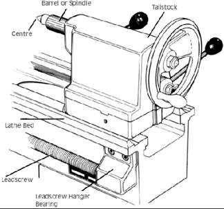
The Tailstock
The tailstock is comprised of two castings. One rests on the ways and may be clamped to the bed in any position to accommodate work of varying lengths. The tailstock spindle is housed in the upper casting which has a sideways adjustment. The tailstock spindle can house centres, drill chucks and other attachments.
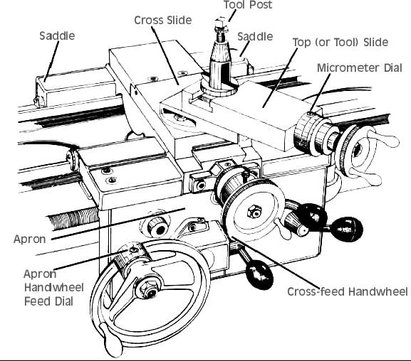
The Carriage
This supports and controls the movement of the cutting tool. This comprises of a saddle that fits over the slides and an apron that hangs in front of the lathe bed. The cross slide is a dovetail way and is located on the carriage. The hand wheel operations for moving the carriage are located on the apron.
The Compound Slide
The compound slide sits on top of the cross slide and has a swivel base. The tool post is located on the compound slide. The path of the cutting tool can be controlled from here so that accurate turning can occur at pre-set angles to the centre axis.
Tool Posts
Tool posts allow the firm positioning and clamping of a cutting tool or cutting tool holder. The common types are the Standard tool post and the square post, shown below.
• Apron: Attached to the front of the carriage, it has the mechanism and controls for moving the carriage and cross slide.
• Feed Rod: Has a keyway, with two reversing pinion gears, either of which can be meshed with the mating bevel gear to forward or reverse the carriage using a clutch.
• Lead Screw: For cutting threads.
• Split Nut: When closed around the lead screw, the carriage is driven along by direct drive without using a clutch.
• Quick Change Gearbox: Controls the movement of the carriage using levers.
• Steady Rest: Clamped to the lathe ways, it uses adjustable fingers to contact the workpiece and align it. Can be used in place of tailstock or in the middle to support long or unstable parts being machined.
• Follow Rest: Bolted to the lathe carriage, it uses adjustable fingers to bear against the workpiece opposite the cutting tool to prevent deflection.
Chucks
Lathe chucks are fitted to the spindle and grip the work.
The Three jaw chuck (self-centring) allows all jaws to move together and as a result
will hold round and hexagonal work accurately on the centre axis.
The four jaw independent chuck has jaws that move independently of each other.
They are designed to hold irregular shapes. With the use of a dial indicator, work can be
held accurately.
The four jaw self centring chuck has the ability to hold square material with a quick
set up time similar to the three jaw chuck.
Centres
Centres are used to support the work axially during turning operations. They are held in place by morse tapers.
Plain centres can be used in both the headstock and the tailstock. They can also be called a dead centre in the tailstock. A large amount of friction can be created so they areless popular than the live centre.
Live centres are used in the tailstock and are more practical as they have bearings housed inside them to reduce friction and allow turning of heavier loads.
The Centre Drill
Work supported by a centre must be drilled so that a bearing is formed. Centre drills are
used for this operation.
Drill Chucks
A drill chuck can be inserted into the tailstock to allow axial drilling of work.
Tool Holders
Tool holders are available in right-hand, left-hand and straight styles. They house the cutting tool for easier mounting on the tool post.
Lathe Tool Material
High speed steel has properties that allow the tool to cut at high speeds. It will retain
the cutting edge at temperatures up to 500 C. They contain elements of carbon,
tungsten, chromium, vanadium, molybdenum and cobalt with the base metal iron.
Tungsten carbide is made with the combination of tungsten with carbon and carbides
of titanium, nickel and cobalt. Tools are made in the form of tips or inserts and are
usually thrown out when they become dull. They can cut up to four times the cutting
speed attainable with high speed steel.
Lathe Tool Angles
The illustration shows the typical angles for a high speed steel tool bit.
Rake is the angle at which the surface of the tool slopes away from the cutting edge.
Clearance is the necessary angle for the face of the tool to clear the work as it rotates.
The cutting edge should be the only part of the tool in contact with the work.
The front cutting angle is the included angle of the tool and is equal to 90 minus the sum of the top rake angle and the front clearance angle.
The side cutting angle is the section angle of the shaped tool bit. It is also known as
the lip angle and is equal to 90 minus the sum of the side rake angle and the clearance angle.
The approach angle affects the life of the tool. It is responsible for the smooth cutting of the tool and generates the swarf curls.
The end relief angle should be large enough to prevent rubbing or binding of the tool against the work.
Machining Operations
Boring is an operation to enlarge and finish holes accurately. This may be done on a lathe or a milling machine.
Boring is a machine operation in which the work is in contact with a single point tool.
A work piece may be held in a 3, 4, or 6 jaw chuck and collets.
Broaching is an operation that completes the cutting in one stroke or cut.
Broaching can be done on both internal and external surfaces.
The teeth of a broaching tool are equally spaced so that as the tool advances into the workpiece, each tooth removes a specified amount of metal.
Drilling is an economical way of removing large amounts of metal to create semi-precision round hole or cavity.

Drilling allows a person to make holes through boards, metals, and other materials.
Used for last removal of stock on preparation for other operations like boring, reaming, or tapping. drill press

A machine designed to hold drill bits which will produce cylindrical holes.

Used for producing cylindrical holes, as well as reaming, boring, counter-boring, counter-sinking, honing, lapping and tapping.
There are three major types:
- Sensitive drill (light drilling)
- Upright drill (heavy duty drilling)
- Radial arm drill press (large, heavy workpieces)
Facing is a lathe operation in which the cutting tool removes metal from the end of the workpiece or a shoulder.

Facing is a machine operation where the work is rotated against a single point tool.
A workpiece may be held in a 3, 4, or 6 jaw chuck, collets or a faceplate.
gang drilling machine Gang drilling machine performs a number of drilling operations in a sequence.
The gang drilling machine is a series of single spindle drill heads mounted on a long table.
Each head is equipped with a different tool to drill the part being machined as it moves from one station to the next.
Grinding is an operation in which the cutting is done by the use of abrasive particles.
Grinding processes remove very small chips in very large numbers by cutting the action of many small individual abrasive grains.
The abrasive grains are formed into a grinding wheel.
Very smooth surfaces can be accomplished by the use of the proper grinding wheel.
grinding machine Grinding machine machines metal parts with an abrasive wheel which can grind to close tolerances.
Grinding machines can produce parts of the identical size, shape, and finish quality.
Various types of grinding machines:
- Plain Surface grinders
- Rotary Surface grinders
- Tool & Cutter grinders
- Universal grinders
- Internal grinders
Gun drilling machine is a machine used to produce long, deep holes.
The operation is called "Gun drilling".
In some drilling machines, the gun drill is held firm in a machine and the workpiece revolves; in other cases the work is stationary and the tool revolves.
Uses three types of spindles for producing deep holes:
- way
- quill
- fixed-spindle
honing
Honing is an internal cutting technique that uses abrasives on a rotating tool to produce extremely accurate holes that require a very smooth finish.

Honing operation
Similar to lapping where abrasive sticks are mounted in a rotating tool.
Capable of accuracies of less than 1/10,000th of one inch. horizontal milling
machine
A horizontal milling machine uses a rotating tool to produce flat surfaces.
Used for heavy stock removal.
The milling machine provides cutting action with a rotating tool.
The spindle is mounted on a horizontal position. Available in different size tables.
lathe The lathe is used for producing cylindrical work. The workpiece is rotated while the cutting tool movement is controlled by the machine.

The lathe is primarily used for cylindrical work.
The lathe may be used for:
boring, drilling, tapping, turning, facing, threading, polishing, grooving, knurling, trepanning
non-precision grinding Non-precision grinding is a cutting technique used when the grinding does not need to be accurate.

Non-precision grinding is done when accuracy is not important.
Non-precision grinding is a free-hand operation done on a pedestal or bench grinder. precision grinding Precision grinding is a cutting technique used when close tolerances and very smooth finishes are required.

Precision grinding as often used as a finish machining process.
Precision grinding allows very small amounts of material to be removed from a workpiece. This is extremely useful in acquiring smooth fnishes.
Reaming is a sizing operation that removes a small amount of metal from a hole already drilled.

The reamer is the tool used for this operation.
Machinists may use hand or machine reamers depending on the job they are performing.
Source: http://rajeshranjan.yolasite.com/resources/machenics/Study%20of%20Lathe.doc
Web site to visit: http://rajeshranjan.yolasite.com/
Author of the text: indicated on the source document of the above text
If you are the author of the text above and you not agree to share your knowledge for teaching, research, scholarship (for fair use as indicated in the United States copyrigh low) please send us an e-mail and we will remove your text quickly. Fair use is a limitation and exception to the exclusive right granted by copyright law to the author of a creative work. In United States copyright law, fair use is a doctrine that permits limited use of copyrighted material without acquiring permission from the rights holders. Examples of fair use include commentary, search engines, criticism, news reporting, research, teaching, library archiving and scholarship. It provides for the legal, unlicensed citation or incorporation of copyrighted material in another author's work under a four-factor balancing test. (source: http://en.wikipedia.org/wiki/Fair_use)
The information of medicine and health contained in the site are of a general nature and purpose which is purely informative and for this reason may not replace in any case, the council of a doctor or a qualified entity legally to the profession.
The texts are the property of their respective authors and we thank them for giving us the opportunity to share for free to students, teachers and users of the Web their texts will used only for illustrative educational and scientific purposes only.
All the information in our site are given for nonprofit educational purposes