
Manual metal arc welding was first invented in Russia in 1888. It involved a bare metal rod with no flux coating to give a protective gas shield. The development of coated electrodes did not occur until the early 1900s when the Kjellberg process was invented in Sweden and the Quasi-arc method was introduced in the UK. It is worth nothing that coated electrodes were slow to be adopted because of their high cost. However, it was inevitable that as the demand for sound welds grew, manual metal arc became synonymous with coated electrodes.
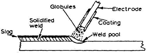
When an arc is struck between the metal rod (electrode) and the workpiece, both the rod and workpiece surface melt to form a weld pool. Simultaneously melting of the flux coating on the rod will form gas and slag which protects the weld pool from the surrounding atmosphere. The slag will solidify and cool and must be chipped off the weld bead once the weld run is complete (or before the next weld pass is deposited).
The process allows only short lengths of weld to be produced before a new electrode needs to be inserted in the holder. Weld penetration is low and the quality of the weld deposit is highly dependent on the skill of the welder.
Ultra-violet rays will burn the skin. It is most definitely not similar to sun tanning.
Arc-welding produces large amounts of hot sparks which will set flammable clothing alight.
The steel metal plate used are heavy and sharp. Wear steel toe-cap boots.
Sparks will set casual tops alight
Arc-welding produces heat, glare, sparks, ultra-violet & infra-red rays and harmful fumes. Welding gauntlets must be worn at all times. Face masks are designed to deflect fumes and should therefore be held close to the face. Gas welding goggles will not afford protection for the face against the light intensity or the radiation and must not be used. Shade 11 EW filters are required in the face mask for manual metal arc welding. Always wear protective goggles when chipping slag.
Ventilation at source, when welding inside buildings, is a formal factory regulation and is there to protect the operator and others. Welding of some materials (i.e. galvanised steel) produces highly toxic fumes
Remember when you are welding behind a dark face mask you will be unaware of what is happening around you. Clear the surroundings of flammable material and ensure there is a fire extinguisher available.
Check for any loose connections that would cause arching thereby creating a hazard. Ensure your surroundings are dry and where possible stand on a timber “duck-board”.
Tanks which have contained flammable material may still hold traces of the substance within the seams.
Containers such as this (i.e. petrol tanks, solvent tanks) should be thoroughly purged with running water
Striking the arc will prove difficult and toxic fumes will be produced
Before welding, ensure others are protected from the light rays by erecting screens. Ultra-violet rays cause the condition known as “arc-eye” which is really conjunctivitis. If affected, the eyes should be thoroughly washed with an eye bath. If the condition persists, medical advice should be sought.
An individual who has been electrocuted could still be in contact with the power source and therefore should be removed with the use of non-conducting material to protect the rescuer.
Onlookers to the welding process must be informed of the need to wear protective clothing.
Effective for all types of fires but not to be used adjacent to live high voltage. The gas is poisonous. Not to be used in confined spaces.
May be used on electric motors, switchgear and transformers up to 10 KV.
Suitable for oil fires but is a conductor and should not be used on live electrical equipment.
Engineering drawings are descriptions of manufactured objects in terms of shape. surface, finish and material. In many industries it is customary to draw the shape of the component without indicating how that shape is achieved. The drawing is a description of a requirement produced by the designer for the instruction of the manufacturer. In theory, the manufacturer knows best how to produce an object with the resources he has. In practice, of course. the designer compromises and produces designs which are capable of production by the techniques ,of which he is aware. For example, a round hole can be drilled, bored or punched. and can be finished by reaming, but whichever method is used, the lines on the drawing are the same and whichever method is used, the material is not changed in its characteristics.
A welded joint offers a range of considerations which do not arise in other forms of manufacture. Firstly, there are far more techniques for making a welded joint than in many other manufacturing operations. This means that the designer has far less chance of foreseeing the manufacturer’s methods. Secondly, the properties and integrity of the joint will depend on the manner in which the weld is made Despite this, the designer can still indicate the type of joint he requires. provided that he is prepared to accept that he may not be able to completely define the joint in the earlier stages of a design.
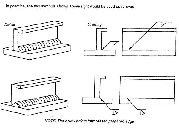
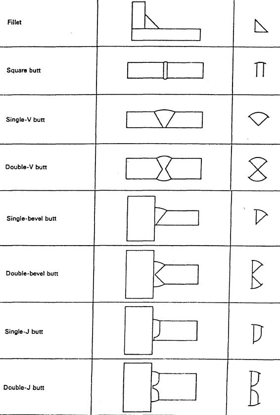
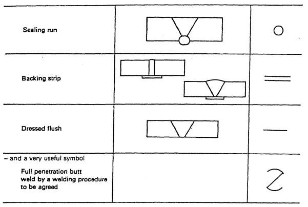
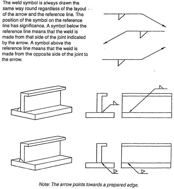
In some industries it is customary for the manufacturer to produce shop drawings which contain details of weld preparations and reference to established welding procedures not shown in detail on the designer’s drawings. The range of British Standard symbols which can be used on a drawing to indicate a weld detail are described here.


Weld size can be indicated on the symbol. 6 mm fillet weld. The drawing must state whether a throat or leg dimension is quoted.

Unequal leg fillet weld. This must be defined by leg length. A diagram of weld ) shape is required here.
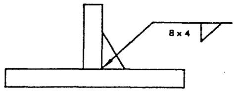
A diagram is not required here because the size of the members indicates the weld orientation.
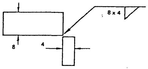
Information other than weld size may be written to the right of the symbol.
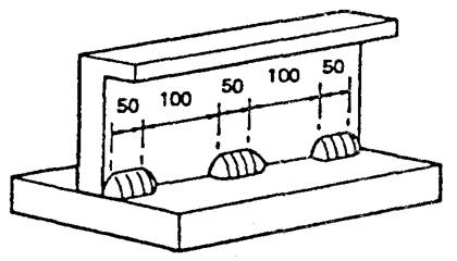
The figure in brackets is the space length. 50 before (100) indicates that the weld is at the beginning. (100) 50 would indicate a space first then a weld although such an arrangement would not represent good practice.
When two wires which form part of an electrical circuit are brought together arid then pulled slowly apart, an electric spark is produced across their ends.
This spark, or arc as it is called, has a temperature of up to 3,600°C. As the arc is confined to a very small area it can melt metal almost instantly.
If one of these wires is connected to the job and the other to a wire rod or electrode, as it is usually called, the heat of the arc melts both the metal of the job and the point of the electrode. The molten metal from the electrode mixes with that from the job and forms the weld. It is important to realize that tiny globules of the molten metal from the electrode are forced through the arc (they do not fall by gravity). If this were not so it would be impossible to use this process for overhead welding.
Manual metal arc welding equipment To create the arc discussed earlier it is necessary to have a voltage to drive the current (which supplies the required heat) through the circuit. A voltage of between 60 and 100 V is required to create the arc, but once it has been obtained only 20—40 V are required to maintain it.
The following stages occur when creating an arc:
With the welding plant switched on, N0- or Open-circuit voltage and before welding commences, no current passes through the leads and the arrimeter reads zero. A voltage has been applied to the circuit, however, and the voltmeter will read the open-circuit or no-load voltage (i.e. between 60 and 100 V).
When the electrode is brought into contact with the job a large current, called the short-circuit current, passes through the leads, and the ammeter will deflect a large amount. While this is happening, however, the voltage drops almost to nothing. The tip of the electrode becomes hot because of the resistance created between it and the job.
If the electrode is slightly withdrawn an arc is formed between the electrode and the job. The air between the two conducts the welding current. As the arc is formed the voltage rises to between 20 and 40 V and the current falls to the value to which it has been set (i.e. the welding current).
The arc is then in the normal welding condition. The heat generated by the arc melts both the workpiece and the electrode, and metal is deposited in the weld pool. During the depositing of the weld metal, variations in both the voltage and current of the arc can occur and the welding plant must be capable of coping with these changes.
If the current value is too low the resulting weld has poor penetration, due to the lack of heating to create complete fusion. The weld filler metal tends to heap up on the surface of the plate without fusing to it and the arc has an unsteady sputtering sound.
When the current value used is too high the electrode becomes red hot and a large amount of spatter takes place. This can result in blowholes being formed in the plate, excessive penetration resulting in weld metal beads on the underside of the plate, undercut along the edge of the weld and excessive oxidation and slag which is hard to remove. The arc has a fierce crackling sound.
With the correct current the arc has a steady crackling sound. The weld formed has good penetration and is easily controlled.
The arc length is the distance between the tip of the electrode and the surface of the weld pool. It should be approximately equal to the diameter of the wire core of the electrode being used. When this distance is correct the electrode metal is deposited in a steady stream of metal particles into the weld pool. If the arc length is reduced it becomes difficult to maintain the arc, due to the increase in welding current that takes place, and it can result in the electrode becoming welded to the weld pool. Also, if the arc length is increased the welding current is reduced, resulting in a poor weld being produced, and the protective gas shield produced from the electrode surrounding the weld pool cannot efficiently prohibit the formation of oxides, etc., in the weld.
A fast rate of travel results in a thin deposit of the filler metal and can result in insufficient fusion of the filler metal with the base metal. The surface of the weld has elongated ripples and a porous crater.
Too slow a rate of travel gives a wide thick deposit of the filler and it can allow the slag to flood the weld pool making it difficult to deposit the filler metal. The surface of the weld appears as coarse ripples and has a flat crater.
Lack of penetration is the failure of the filler metal to penetrate into the joint. It is caused by:
Lack of fusion is the failure of the filler metal to fuse with the parent metal. It is caused by:
Porosity is a group of small holes throughout the weld metal. It is caused by the trapping of gas during the welding process, due to chemicals in the metal, dampness, or too rapid cooling of the weld.
Slag inclusion is the entrapment of slag or other impurities in the weld. It is caused by the slag from previous runs not being cleaned away, or insufficient cleaning and preparation of the base metal before welding commences.
Undercuts are grooves or slots along the edges of the weld caused by:
Overlays consist of metal that has flowed on to the parent metal without fusing with it. The defect is caused by:
Cracking is the formation of cracks either in the weld metal or the parent metal. It is caused by:
Blowholes are large holes in the weld caused by:
Burn through is the collapse of the weld pool due to:
Excessive penetration is where the weld metal protrudes through the root of the weld. It is caused by:
As has been seen earlier, when a piece of metal is heated it expands and, on cooling down, contracts. With welding and cutting processes the heating takes place over a localized area of the metal and expansion can only take place in that portion of the metal. The subsequent contraction that takes place on cooling can result in forces causing distortion or, even worse, cracking of the metal. When a weld bead is deposit ed on the joint between two plates, the molten metal passing through the arc is at a very high temperature. The arc melting the edges of the joint and the filler and base metal fuse together. As the arc moves across the joint the deposited bead starts to cool and considerable contraction forces are set up in the weld area.
As the deposited metal was at a higher temperature than the parent metal it will contract more and also, since its volume is greater, there is a large volume of metal shrinkage. The result is distortion of the joint. The following are several ways of controlling the effect of distortion during welding; presetting; backstepping or stepwelding, jigging, and preheating. They are described and shown below:

When a piece of metal is heated in the atmosphere it combines with the oxygen and nitrogen to form oxides and nitrides which combine with the metal. If these were allowed to form in the weld it would result in a poor quality, weak and brittle weld.
It is therefore necessary to protect the weld area from the air. This can be done either by surrounding the weld area by an inert gas or by the use of suitable fluxes.
It is usual, with manual metal arc welding, to use coated electrodes. These electrodes consist of a metal core surrounded by a layer of suitable flux coating.
The six main functions of the electrode coating are as follows:
The method of classifying of electrodes is based on the use of a four-digit number, preceded by the letter ‘E’ for ‘Electrode’.
The first two digits designate the minimum tensile strength of the weld metal (in 1,000 psi) in the as-welded condition.
The third digit indicates the position in which the electrode is capable of making satisfactory welds.
The fourth digit indicates the current to be used, and the type of flux coating.
For example, the classification of E6012 electrodes is derived as follows:
The detail of the classification is shown below:
First and second digits:
Third and fourth digits:
The third and fourth digits indicate positional usability and flux coating types e.g.
REMEMBER: WELDING RAYS ARE VERY DANGEROUS. ALWAYS WEAR A WELDING SHIELD.
When a welding flash causes arc rays to come into contact with unprotected eyes, the injury is called arc flash. This usually happens if the helmet is raised and an arc is struck during arc welding. If the flash is frequent enough or severe enough, the eyeballs become covered with many small water blisters. The eyelids moving against the eyeballs cause irritation and pain. The eyes are also hurt by bright light and will water profusely. In extreme cases blindness will occur for two or three days. If exposed to arc flash, a welder should wear dark glasses and avoid any welding for several days.
ALWAYS WEAR GOGGLES WHEN CHIPPING SLAG AS IT WILL BE HOT AND SHARP.
ALWAYS SCREEN YOUR WELDING FROM OTHERS TO AVOID RISK OF ARC FLASH .
NEVER WELD AN ENCLOSED TANK UNTIL THE FOLLOWING PRECAUTIONS HAVE BEEN TAKEN:
ALWAYS EXAMINE WELDING CABLES FOR DAMAGE PEPORT.
With this system the current passes in one direction only. The heat generated is split into two parts, two-thirds goes to the positive pole and one-third to the negative pole. This is important as it determines the design of the electrode to be used.
If a light-coated electrode is connected to the positive terminal it quickly becomes too hot to use for welding. But if the workpiece is connected to the positive terminal and the electrode to the negative terminal, the weld pool becomes the hottest part and the electrode stays beneath its critical heat value.
The polarity of the electrode, when using d.c. for welding, is most important and the electrode manufacturer’s recommendations should be strictly adhered to, except in exceptional circumstances where the work must be kept as cool as possible. The terms used by British Standards for electrodes state that:
Electrodes connected to the positive terminal are called electrode positive, and electrodes connected to the negative terminal are called electrode negative.
Basic equipment— (1) a generator driven either from d.c. mains (motor generator) or by a petrol or diesel engine; (2) an a.c./ d.c. motor generator set; or (3) rectifying equipment.
The generator must supply an open-circuit voltage of about 60 V which will drop to approximately 20 V when the arc is struck. Generators can be obtained with various current ratings from 100 to 600 A, and the modern types automatically adjust themselves to allow for the voltage fluctuations of the arc. Normally only one welder can work from a set.
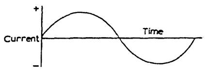
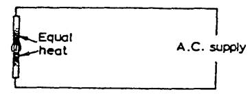
With a.c., the direction of the current flow continually changes. This reverse in direction takes place 50 times per second. Because of this reversal of the current flow the two poles are maintained at the same temperature, and reversal of the terminals has no effect as is the case with d.c.
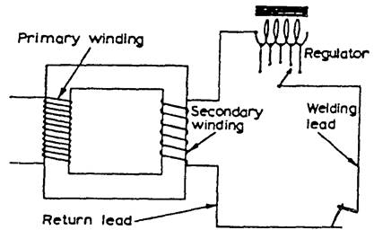
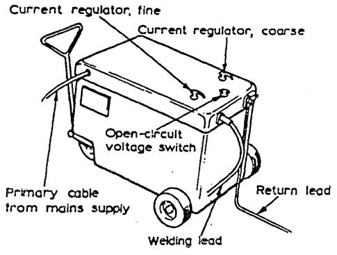
The a.c. plant consists of a transformer which will reduce the supply voltage down to the required open-circuit voltage, i.e. 60 - 100 V. Various types of set are available giving different current ranges. Depending on the set, current values from 20 A up to 500 A can be obtained.
Alternating-current welding plant is cheaper to buy than the equivalent direct current set, requires less maintenance, is quieter in operation, and the running costs are lower. The use of a.c. equipment is dependent upon an a.c. supply being available, and therefore when welding on sites it is not usually possible and a d.c. engine-driven generator is used.
When the welder strikes his arc the welding generator is subjected to a short circuit and the current passing through the windings of the generator increases. If this increase in current is not controlled the windings will overheat, resulting in damage to the generator. In most cases this short-circuit current should not exceed 150% of the normal welding current and overload devices are fitted to protect the equipment.
“Arc Blow” is encountered with D.C welding equipment. The arc is forced away from the weld point notably when welding in corners. The conductors carrying the current namely the welding lead from the set, and the return lead from the work piece are carrying current in opposite direction so that a repulsive magnetic force is set up which effects the D.C. Welding Arc.
This conditions occurs most when using currents above 200 or below 40 amps. The best method of connections are:
Alternating current is the primary form of electrical power supplied to domestic and industrial users. It has no fixed polarity and alternates between positive (+) and negative (-) at approx. 50 to 60 cycles per second. It is the most common form of power used when welding mild steel.
Direct current flows in a straight line from positive to negative continuously. Approx. 60% of the heat generated is at the positive pole. This feature is used to advantage when welding cast iron. Ferrous and non-ferrous metals can be welded with D.C. It is the most common form of power used on site where grid power is not available. Welding with D.C. can produce “arc-blow” which is a phenomenon which causes the globule of metal transferring from the electrode to waver. If contained it has no negative effect on the finished weld. Moving the return cable further from the arc will reduce the effect.
Manual Metal Arc welding electrodes are manufactured with a deoxided core wire surrounded with an appropriate coating or “flux”.
The coating:
ELECTRODES COME IN A RANGE OF SIZES:
Electrodes for welding mild steel should be kept dry to avoid the possibility of porosity. They should be kept in the packet in which they came to ensure correct identification and to avoid damage to the coating.
They should not be bent to avoid breaking of the coating and subsequent contamination of the weld.
FAULT |
DESCRIPTION |
CAUSES |
Porosity |
A group of trapped gas pores |
Contamination of parent metal or filler metal. Moisture trapped between surfaces. Too rapid cooling of parent metal. |
Slag Inclusion |
Slag trapped in weld. |
Welding current too low. Gap too close. Incorrect angle. Electrode too large. |
Lack of Fusion |
Discontinuity of weld or failure to secure weld. |
Welding current too low or inadequate heat. Too rapid travel of the electrode. |
Lack of penetration |
Failure of weld metal to extend into or fill the root of the weld. |
Unsuitable edge or joint preparation. Current too low. Incorrect welding technique. |
Undercutting |
A groove or hollow cut in the surface or fusion face of the parent metal at the toe of a run. |
Wrong manipulation of the electrode. Moving the electrode too quickly over heating area. Welding current too high. Arc too long. |
Excess spatter |
Tiny globules of unfused filler metal splashed around weld area. |
Current too high. Gap too long. |
Unequal leg length |
Distance from toe to root unequal in fillet or lap weld. |
Incorrect electrode angle. |
F = Flat / Downhand.
H = Horizontal / Vertical.
V = Vertical (upwards).
D = Vertical (down).
O = Overhead.
Source: http://local.ecollege.ie/Content/APPRENTICE/liu/Plumbing_notes/Manual_Arc_Welding_M3_U5.doc
Web site to visit: http://local.ecollege.ie
Author of the text: indicated on the source document of the above text
If you are the author of the text above and you not agree to share your knowledge for teaching, research, scholarship (for fair use as indicated in the United States copyrigh low) please send us an e-mail and we will remove your text quickly. Fair use is a limitation and exception to the exclusive right granted by copyright law to the author of a creative work. In United States copyright law, fair use is a doctrine that permits limited use of copyrighted material without acquiring permission from the rights holders. Examples of fair use include commentary, search engines, criticism, news reporting, research, teaching, library archiving and scholarship. It provides for the legal, unlicensed citation or incorporation of copyrighted material in another author's work under a four-factor balancing test. (source: http://en.wikipedia.org/wiki/Fair_use)
The information of medicine and health contained in the site are of a general nature and purpose which is purely informative and for this reason may not replace in any case, the council of a doctor or a qualified entity legally to the profession.
The texts are the property of their respective authors and we thank them for giving us the opportunity to share for free to students, teachers and users of the Web their texts will used only for illustrative educational and scientific purposes only.
All the information in our site are given for nonprofit educational purposes