
This is an important function which can be divided into four categories:
Taking (a) and (c), this usually applies when the client, due to extended material deliveries, purchases the material well in advance of issuing the contract for tender. In many cases, particularly on a large contract, the client desires to reserve capacity before drawings are completed and he therefore invites pipework contractors to submit a schedule of rates and this gives the approximate tonnage, footage, sizes, specifications, type of material, and type of drawings which will be provided (either isometric or general arrangements) and fabrication and erection program.
From this information the contractor can compile rates which give prices for all operations such as welds, bevels, bending, etc. On the basis of this information the client can place his order well in advance of completion of design and detailed drawings and the contractor also has some idea of the capacity he requires to reserve in his workshop and the labour required for erection.
In other cases the client has all details complete before going out to tender and here the contractor can give an accurate lump sum price backed by a schedule of rates for the various operations, these being used if alterations to design are made after the order is placed. Usually where erection is involved, a site visit is necessary to study site conditions, rates of pay applying on site and available access.
The ability of a material to return to normal after being pulled and pushed out of shape. Rubber is an excellent example of a material which is elastic. Metals are basically not elastic, although some steels, hard brass and hard copper can be made into spring shapes which possess certain characteristics of elasticity.
This represents the ability of a material to resist wear and tear. A durable material is one which is long-lasting and non-perishable.
This is the melting point of a material and indicates the temperature at which a solid changes to a liquid. Metals being welded have to be heated to the melting point of the material in order to "fuse" together with the filler rod. Mild steel has the highest melting point of all the plumber's metals. Although unyielding at normal temperatures, when heated to red heat it can easily be bent.
The ability of a metal to be worked (bossed or hammered) into a new shape without breaking. Lead has this property to a remarkable degree. Most metals become more malleable when their temperature is increased.
This denotes the ability of a metal to be stretched without breaking. A good example of a ductile metal would be copper which can be drawn out to form tubes and wires.
A material's ability to resist being pulled apart or pulled from its present position.
This is a measure of the tenacity contained by a material. A sample piece of material is bolted between two clamps in a special tensile strength testing machine. The clamps are then made to pull apart in opposite directions, thus imposing a pulling load on the sample. The sample slowly stretches and eventually breaks. The force at which the material breaks is a measure of its tensile strength and is expressed in N/m².
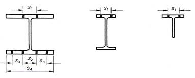
Table 1 - Recommended Spacing of Holes in Columns, Beams and Tees to BS 4:Part 1:1972
Note: That the actual flange width for a universal section may be less than the nominal size and that the difference may be significant in determining the maximum diameter.
The dimensions S1 and S2 have been selected for normal conditions but adjustments may be necessary for relatively large diameter fastenings or particularly heavy masses of serial size.
b min. This is the minimum width of flange to comply with the table above of BS 449:Part 2:1969.
Table 2 - Recommended Back Marks for Holes in Channels to BS 4: Part 1:1972

These angles are those metric sizes selected, from the full list recommended by the ISO, as British Standard Metric Angles.
Note that HSFG bolts may require adjustments to the backmarks shown due to the larger nut and washer dimensions.
Inner gauge lines are for normal conditions and may require adjustment for large diameters of fasteners or thick members.
Outer gauge lines may require consideration in relation to a specified edge distance.
Table 3 - Recommended Back Marks for Standard Angles to BS 4:Part 1:1972
The stiffness and rigidity of square-cornered frames may be considerably increased simply by welding, bolting or riveting diagonal members across the corners. The diagonal members also help to ensure squareness. Several of these identical units may be joined to provide very strong rigid frames. It is important from a safety point of view that diagonal members are securely fastened before lifting and erecting to prevent collapse. The two common types of welded connection are the mitre corner and the notched corner, the notched corner being more favourable as location is provided and distortion due to welding is minimised.
Sketches of these two types of corner joint are shown in Figure 2.
Figure 2 - Corner Joint Types
If the foot of the stanchion were not square to the base plate, the total load on the stanchion would be carried through the bolt shanks or rivets, in the case of bolted or riveted assemblies.
Figure 3 - Stanchion Bases
Splices in stanchions or columns should be arranged at a position above the adjacent floor level so that the joint, including any splice plates are well clear of any beam connection. Splices should never be made on a connection otherwise the bolts making the joint will be subjected to double loading. Figure 4 illustrates stanchion splices.
Figure 4 - Stanchion Splices
Figure 5 illustrates simple beam to stanchion connections. It will be noticed that the entire load is transmitted from the beam to the stanchion through the seating cleat and its fixings.
Figure 5 - Connection of Beams to Stanchions
Where beam to beam connections are made, web cleats or an end plate are used to transmit loads from the secondary to the main beams.
Figure 6 illustrates this type of connection.
Figure 6 - Beam to Beam Connections
Roof trusses are plane frames consisting of sloping rafters which meet at the ridge. A main tie connects the feet of the rafters, and the internal bracing members. They are used to support the roof covering in conjunction with purlins. Purlins are secondary members laid longitudinally across the rafters to which the roof covering is attached.
Lattice girders, also sometimes called 'trusses', are plane frames of open-web construction. They usually have parallel chords or booms which are connected with internal web bracing members. There are two basic types of lattice girder, the 'N' type and the 'Warren' type.
As with roof trusses, the framing of a lattice girder should be triangulated, taking into account the span and the spacings of the applied loads. The booms are divided into panels of equal length and, as far as possible, the panel points are arranged to coincide with the applied loads. Lattice girders may be used in flat roof construction or in conjunction with trusses or trussed rafters.
Because of the greater forces usually borne by members of lattice girders, shop connections are generally riveted or welded. Site connections are normally made with HIGH-STRENGTH FRICTION-GRIP BOLTS (which have largely replaced rivets for site work) or by welding.
Web stiffeners are required when a beam or plated structure is subjected to a twisting force (TORSION) or a sideways thrust.
The need for web stiffeners, or gussets, increases as the depth of the beam increases.
Web stiffeners may be welded or riveted. When fabricating stiffeners which are to be welded in position, it is important that the stiffener is an exact fit on the beam. The slope of the tapered flanges should be copied faithfully. With triangular-shaped gussets 'feather edges' must be avoided, the sharp corners should be cut off, for otherwise the strength of the assembly may be reduced rather than increased. Another important reason for cutting off the corners of webs or gussets is to provide ample clearance from fillet welds or bending radii. This allows for ease of assembly and permits welding through the gap with the web, or gusset, in position. It also avoids costly fitting operations at the corners.
Figure 7 - Roof Trusses
Figure 8 - Lattice Girders
Bar frames or open web beams are of ultra-light construction and are particularly suitable for use as long-span roof purlins. The flanges are usually formed of angle sections and the web diagonals of round or square sections, bent to shape and welded to the flanges.
Figure 9 - Construction of Lattice Girders
Figure 10 - Use of Applied Stiffeners
Figure 11 - The Use of Angle Stiffeners
The material most commonly used in constructional steelwork is mild steel to BS 4360, which is produced by steel rolling mills in a variety of shapes and sizes, some of which are illustrated in Figure 12.
Figure 12 - Typical Structural Steel Sections
For efficiency a structural member should use as little material as possible to carry as much load as possible.
The I-section, extensively used in steelwork, is designed to give an efficient STRENGTH/WEIGHT ratio, and the 'universal sections' provide even better efficiency.
In constructional steel work the connections of the members are made by one of the following four methods:
Basically a steel structure is so designed that the sizes of the various components are determined by their ability to withstand the effects of the applied loads in service.
R. S. A. R. S. U. A.
O T N O T N N
L E G L E E G
L E L L E Q L
E L E E L U E
D D A
L
E.g. 50mm x 50 angle E.g. 70mm x 30 angle
Or symbol < or symbol <
Figure 13 - Workholding for Riveting
'Plate dogs' and 'pins' are used extensively in the plate working and steel fabrication workshops for a variety of forming and straightening operations. They are used to clamp plates, sections and plate formers on to the bending floor. The bending floor or bending table consists of a large cast iron slab which has numerous location holes in which the 'dogs' and 'pins' are inserted.
The basic principle of the use of these devices is illustrated by two practical applications: bevelling steel section (Figure 15); and the hot bending of angle section (Figure 15).
In the assembly of parts prior to welding, clamps of many types are needed. G clamps are most commonly used, but care must be taken to prevent 'spatter' from damaging the threads, otherwise the useful life of an ordinary G clamp will be extremely short. This can be done by coating the threads with 'anti-spatter compound'.
Because of the damage which can be caused by 'spatter', the special G clamps have a very definite advantage over ordinary G clamps by the fact that they are fitted with a shield which protects the screw against damage and spatter.
Figure 14 - Use of Soft Iron Wire and Spring Pegs for Holding Work
Figure 15 - Applications of Plate-Dogs and Pins for Workholding
Figure 16 - Quick-Acting Clamping Devices
Many of the clamps used for holding work for welding are quick-acting and can be rapidly adjusted for various thickness of workpiece. Quick-acting clamps are essential where work has to be assembled in welding jigs for batch production. Ordinary screw-type clamping devices would be uneconomical and time consuming. Quick-acting clamps are generally of the 'toggle-action' type or 'cam-operated'. Typical examples of these quick-acting clamping devices are shown in Figure 16.
Various other clamping devices in common use for holding work prior to welding include, wedges, clamps and angle bars, cleats, U-clamps or bridges, strong-backs, jack-clamps, and chain-and-bar. These will now be discussed in detail.
When parts are set up prior to welding, it is important that the plate edges should be correctly aligned. The root faces should be aligned and the root gaps uniform. Many devices may be used to achieve this alignment, one of which is called a 'strong-back'.
Basically, a strong-back consists of a rigid piece of plate or angle-section which is tack-welded in position on one side of the joint and used in conjunction with a wedge or a bolt and dog, as shown in Figure 17.
Figure 17 - The Use of Strong Backs for Welding
Angle cleats are used to push or draw the plate edges together when assembling long and circular weld seams. When used for pulling the joint edges together, they are often referred to as 'draw-lugs'.
Applications showing the basic principle involved are illustrated in Figure 18.
Figure 18 - The Use of Cleats for Holding Work for Welding
Glands are simple rigid bridge pieces which are usually used in conjunction with cleats as an aid to assembly. Whereas cleats are used to maintain the correct uniform gap between the joint edges of the plates, glands provide the means of lateral alignment, as shown in Figure 19.
Figure 19 - Use of Glands
Dog bolts or gland screws are positioned on one side of the joint and tack-welded to the plate.
The glands (bridging pieces) are placed in position and held by means of washers and nuts, as shown in the diagram.
The gland nuts are tightened and adjusted with a spanner until the desired alignment of the joint to be welded has been achieved. On completion of the welding operation, these useful assemblies are dismantled, and the tack-bolts removed.
An effective method of clamping a stiffener, such as an angle bar, in position on the plate prior to welding, is to make use of a clamping dog and wood blocks. A bolt is tack-welded adjacent to the required location of the stiffener, and the assembly is held in position as shown in Figure 20. On completion of the welding, the bolt is removed by breaking the tack welds, and the local surface cleaned up with an angle grinder - this applies to any assembly aid which is tack-welded on to the workpiece.
Figure 20 - Application of the Use of Clamping Dogs
Bridge pieces are commonly referred to as U-clamps, and are used together with wedges for clamping sections and plates together, as shown in Figure 21.
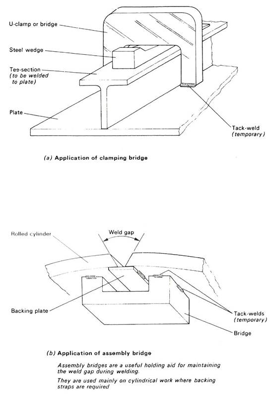
Figure 21 - Use of Bridge Pieces
Difficulty is often expressed when welding longitudinal seams on cylindrical vessels which have been incorrectly rolled, causing considerable misalignment of the joint edges. This difficulty may be overcome by the use of a chain and bar, as illustrated in Figure 22.
This effective method may also be applied to flat plates which are not of alignment.
Figure 22 - Use of Chain and Bar
Jack clamps are used for the attachment and alignment of heavy plate. An example of its use is shown in Figure 23(a). It will be seen that it makes use of the principle of moments. Figure 23(b) shows how this principle is applied to the jack clamp.
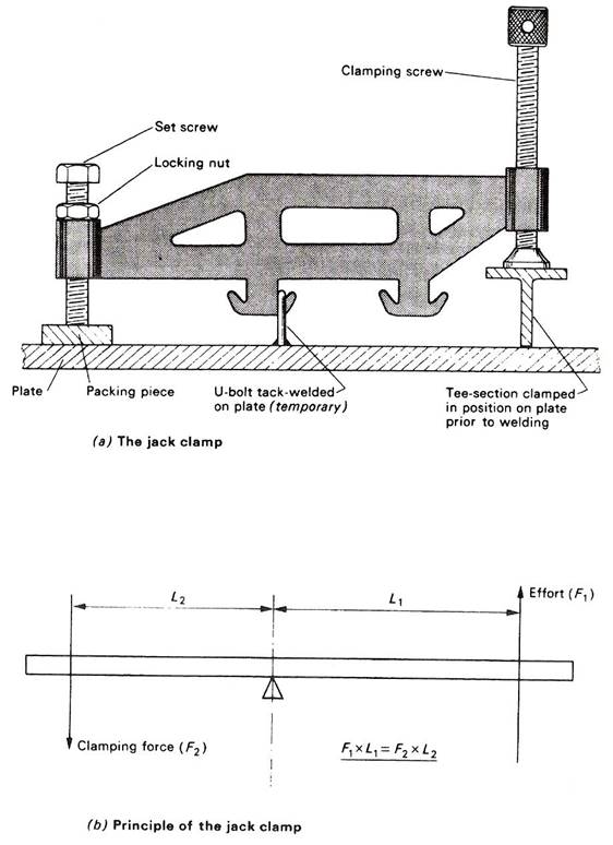
Figure 23 - Use of Jack Clamps for Holding Work
Large cylindrical vessels are often made up of two or more sections of rolled plate. The sections are then welded together circumferentially. It is essential that each section is truly circular to ensure correct alignment of the joint to be welded.
In order to provide correct alignment of the circumferential joints, 'spiders' are fitted at both ends of each section to ensure concentricity. Figure 24 illustrates the use of spiders for this purpose.
Figure 24 - Use of Spider Assemblies for Holding Work
The spider assemblies are positioned both ends of the rolled and welded steel cylinder with the aid of suitable lifting tackle.
Steel packing pieces are placed between the set screws, on the ends of the legs, and the cylinder wall.
The set screws are tightened and adjusted in sequence until the ends of the cylinder are truly circular.
Once the contour has been checked by means of a suitable template, location plates are tack-welded to the legs and the inside cylinder wall.
When tack-welding clamping aids such as cleats, bridges, strong-backs and dogs, the tack welds should be small, but sufficient to perform their temporary function. They should be made so that they can be easily removed after they have served their purpose.
These clamping devices should not be used on hardenable steels because there is a tendency for local hard spots to develop as a result of the small tack welds.
For shop assemblies, a large, flat, rigid base plate with Tee-slots is generally used for bolting-down purposes. Such tables or plates are ideal for the use of Tee-slot clamps. It is common practice to use angle plates and simple framework for holding components in position prior to welding.
On site, a number of the clamping devices discussed in this section are extremely useful for manipulating plates and sections into the correct position and holding them there for welding.
Caliper clamps and magnetic clamps, as shown in Figure 25, are also useful where components have to be welded together at an angle.

Figure 25 - Magnetic Clamps for Welding
Source: http://local.ecollege.ie/Content/APPRENTICE/liu/metalfab_notes/module4/Roof%20Trusses_M4_U4.doc
Web site to visit: http://local.ecollege.ie/
Author of the text: indicated on the source document of the above text
If you are the author of the text above and you not agree to share your knowledge for teaching, research, scholarship (for fair use as indicated in the United States copyrigh low) please send us an e-mail and we will remove your text quickly. Fair use is a limitation and exception to the exclusive right granted by copyright law to the author of a creative work. In United States copyright law, fair use is a doctrine that permits limited use of copyrighted material without acquiring permission from the rights holders. Examples of fair use include commentary, search engines, criticism, news reporting, research, teaching, library archiving and scholarship. It provides for the legal, unlicensed citation or incorporation of copyrighted material in another author's work under a four-factor balancing test. (source: http://en.wikipedia.org/wiki/Fair_use)
The information of medicine and health contained in the site are of a general nature and purpose which is purely informative and for this reason may not replace in any case, the council of a doctor or a qualified entity legally to the profession.
The texts are the property of their respective authors and we thank them for giving us the opportunity to share for free to students, teachers and users of the Web their texts will used only for illustrative educational and scientific purposes only.
All the information in our site are given for nonprofit educational purposes