
SECTION 4 METHODS OF STRUCTURAL ANALYSIS
4.1 Methods of Determining Action Effects
4.1.1 General – For the purpose of complying with the requirements of the limit states of stability, strength and serviceability specified in Section 5 effects of design actions on a structure and its members and connections, shall be determined by structural analysis using the assumptions of 4.2 and .4.3 and one of the following methods of analysis:
a) Elastic analysis in accordance with 4.4
b) Plastic analysis in accordance with 4.5 or
c) Advanced analysis in accordance with Appendix C.
The design action effects for design basis earthquake loads shall be obtained only by an elastic analysis. The maximum credible earthquake loads shall be assumed to correspond to the load at which significant plastic hinges are formed in the structure and the corresponding effects shall be obtained by plastic or Advanced Analysis. More information on analysis to resist earthquake is given in Section 12 and IS: 1893.
4.1.2 Non-sway and Sway frames – For the purpose of analysis and design, the structural frames are classified as non-sway and sway frames as given below:
i) For clad frames where the stiffening effect of the cladding is not taken into account in the deflection calculations:
![]()
ii) For unclad frame or clad frames where the stiffening effect of the cladding is taken into account in the deflection calculations:
![]()
where
hs = storey height
4.2 Forms of Construction assumed for Structural Analysis
4.2.1 The effects of design action in the members and connections of a structure shall be determined by assuming singly or in combination, the following forms of construction:
4.2.1.1 Rigid Construction –In rigid construction, the connections between members (beam and column) at their junction shall be assumed to have sufficient rigidity to hold the original angles between the members connected at a joint unchanged under loading.
4.2.1.2 Semi-rigid Construction – In semi-rigid construction, the connections between members (beams and column) at their junction may not have sufficient rigidity to hold the original angles between the members at a joint unchanged, but shall be assumed to have the capacity to furnish a dependable and known degree of flexural restraint. The relationship between the degree of flexural restraint and the level of the load effects shall be established by any rational method or based on test results.
4.2.1.3 Simple Construction – In simple construction, the connections between members (beams and column) at their junction will not resist any appreciable moment and shall be assumed to be hinged.
4.2.2 Design of Connections – The design of all connections shall be consistent with the form of construction, and the behaviour of the connections shall not adversely affect any other part of the structure, beyond what is allowed for in design. Connections shall be designed in accordance with Section 10.
4.3 Assumptions in Analysis
4.3.1 The structure shall be analysed in its entirety except as follows:
4.3.2 Span Length – The span length of a flexural member in a continuous frame system shall be taken as the distance between centre-to-centre of the supports.
4.3.3 Arrangements of Variable Loads in Buildings – For building structures, the various arrangements of variable loads, considered for the analysis, shall include at least the following:
4.3.4 Base Stiffness – In the analysis of all structures the appropriate base stiffness about the axis under consideration shall be used. In the absence of the knowledge of the pedestal and foundation stiffness, the following may be assumed:
a) When the column is rigidly connected to a suitable foundation, the stiffness of the pedestal shall be taken as the stiffness of the column above base plate.
b) When the column is nominally connected to the foundation, a pedestal stiffness of 10% of the column stiffness may be assumed.
c) When an actual pin or rocker is provided in the connection between the steel column and pedestal, the base stiffness shall be taken as zero and the column be assumed as hinged at base.
4.3.5 Simple Construction – Bending members may be assumed to have their ends connected for shear only and to be free to rotate. In triangulated structures, axial forces may be determined by assuming that all members are pin connected.
4.3.5.1.A beam reaction or a similar load on a column shall be taken as acting at a minimum distance of 100 mm from the face of the column towards the span or at the centre of bearing, whichever gives the greater eccentricity, except that for a column cap, the load shall be taken as acting at the face of the column, or edge of packing, if used, towards the span.
4.3.5.2 In a continuous column, the design bending moment due to eccentricity of loading at any one floor or horizontal frame level shall be taken as:
4.3.6 Notional Horizontal Loads –To check the sway stability of the frame subjected to gravity loads, notional horizontal forces should be applied. These account for practical imperfections and should be taken at each level as 0.5% of factored dead load plus vertical imposed loads applied at that level. The notional load should not be applied along with other lateral loads such as wind and earthquake loads in the analysis.
4.3.6.1 The notional forces should be applied on the whole structure, in both orthogonal directions, in one direction at a time, at each roof and all floor level or their equivalent. They should be taken as acting simultaneously with factored gravity loads.
4.3.6.2 The notional force should not be
a) Applied when considering overturning or overall instability
b) Combined with other horizontal (lateral) loads
c) Combined with temperature effects
d) Taken to contribute to the net shear on the foundation
4.3.6.3 The sway stability effect using notional load need not be considered if the height to lateral width of the building is less than unity.
4.4 Elastic Analysis
4.4.1 Assumptions – Individual members shall be assumed to remain elastic under the action of the factored design loads for all limit states.
The effect of haunching or any variation of the cross-section along the axis of a member shall be considered, and where significant, shall be taken into account in the determination of the member stiffness.
4.4.2 Second-order Effects – The analysis shall allow for the effects of the design loads acting on the structure and its members in their displaced and deformed configuration. These second-order effects shall be taken into account by using either
a) A first-order elastic analysis with moment amplification in accordance with 4.4.3, provided the moment amplification factors (db) or (ds), are not greater than 1.4; or
b) A second-order elastic analysis in accordance with Appendix C.
4.4.3 First-order Elastic Analysis
4.4.3.1 In a first-order elastic analysis, the equilibrium of the frame in the undeformed geometry is considered, the changes in the geometry of the frame due to the loading are not accounted for, and changes in the effective stiffnesses of the members due to axial force are neglected. The effects of these on the first-order bending moments shall be allowed for by using one of the methods of moment amplification of 4.4.3.2 or 4.4.3.3 as appropriate, except that where the moment amplification factor (db) or (ds), calculated in accordance with 4.4.3.2 or 4.4.3.3 as appropriate, is greater than 1.4, a second-order elastic analysis in accordance with Appendix C shall be carried out.
4.4.3.2 Moment Amplification for Members in Non-sway Frames – For a member with zero axial compression or a member subject to axial tension, the design bending moment is that obtained from the first order analysis for factored loads, without any amplification.
For a braced member with a design axial compressive force Pd as determined by the first order analysis, the design bending moment shall be calculated considering moment amplification as in Section 9.
4.4.3.3 Moment Amplification for Member in a Sway Frame –The design bending moment shall be calculated as the product of moment amplification factor, (Section 9.3.2.2 (Ky, Kz)) and the moment obtained from the first order analysis of the sway frame, unless a more detailed analysis is carried out. (Appendix C).
4.4.3.4 The calculated bending moments from the first order elastic analysis may be modified by redistribution upto 15% of the peak calculated moment of the member under factored load, provided that:
a) The internal forces and moments in the members of the frame are in equilibrium with applied loads.
b) All the members in which the moments are reduced belong to plastic or compact section classification (Section 3.7).
4.5 Plastic Analysis
4.5.1 Application – The design action effects throughout or part of a structure may be determined by a plastic analysis, provided that the requirements of 4.5.2 are met. The distribution of design action effects shall satisfy equilibrium and the boundary conditions.
4.5.2 Requirements – When a plastic method of analysis is used, all of the following conditions of this section shall be satisfied, unless adequate ductility of the structure and plastic rotation capacity of its members and connections are established for the design loading conditions by other means of evaluation:
Steels conforming to IS: 2062 shall be deemed to satisfy the above requirements.
4.5.2.1 Restraints –Torsional restraint (against lateral buckling) should be provided at all plastic hinge locations if practicable. Where not feasible, the restraint should be provided within a distance of D/2 of the plastic hinge location, where D is the total depth of section.
The torsional restraint requirement at a section as above need not be met at the last plastic hinge to form, provided it can be clearly identified.
Within a member containing a plastic hinge, the maximum distance Lm from the restraint at the plastic hinge to an adjacent restraint should be calculated by any rational method or the conservative method given below, so as to prevent lateral buckling.

where
fc = average compressive stress on the cross section due to axial load (in N/mm2)
fy = yield stress (in N/mm2)
ry = radius of gyration about the minor axis (in mm)
xt = torsional index,![]()
A = area of cross section
Iw, Iy, It = warping constant, second moment of the cross section above the minor axes and St. Venant’s torsion constant, respectively
Where the member has unequal flanges, ry should be taken as the lesser of the values of the compression flange only or the whole section.
Where the cross section of the member varies within the length Lm, the maximum value of ry and the maximum value of xt should be used.
The spacing of restraints to member lengths not containing a plastic hinge should satisfy the recommendations of section on lateral buckling strength of beams (Section 8.2). Where the restraints are placed at the limiting distance Lm no further checks are required.
4.5.2.2 Stiffeners at Plastic Hinge Locations - Web stiffeners should be provided where a concentrated load is applied within D/2 of a plastic hinge location, which exceeds 10% of the shear capacity of the member (8.2.1.2). The stiffener should be provided within a distance of half the depth of the member, on either side of the hinge location and be designed to carry the applied load in accordance with 8.4. If the stiffeners are flat plates, the outstand width to the thickness ratio, b/t, should not exceed the values given in the plastic section (3.7). Where such sections are used the ratio (Iso/It) 1/2, should not exceed the values given for plastic section (for simple outstand in Section 3.7).
where
Iso = second moment of area of the stiffener about the face of the element perpendicular to the web,
It = St.Venant’s torsion constant of the stiffener.
4.5.2.3 Fabrication Restriction –Within a length equal to the member depth, on either side of a plastic hinge location, the following restrictions should be applied to the tension flange and noted in the design.
4.5.3 Assumptions in Analysis – The design action effects shall be determined using a rigid- plastic analysis.
It shall be permissible to assume full strength or partial strength connections, provided the capacities of these are used in the analysis, and provided that;
In the case of building structures, it is not normally necessary to consider the effect of alternating plasticity.
4.5.4 Second-order Effects –Any second-order effects of the loads acting on the structure in its deformed configuration may be neglected where the elastic buckling load factor (l cr) (4.6) satisfies the condition λcr > 10,
when 5 < λcr <10, second-order effects may be neglected provided, the design load effects are amplified by a factor dp = 0.9/{1-(1/ λcr)}
when lcr<5, a second-order plastic analysis shall be carried out.
4.6.1 The elastic buckling load factor (lcr) shall be the ratio of the elastic buckling load set of the frame to the design load set for the frame, and shall be determined in accordance with 4.6.2.
Note: The value of lcr depends on the load set and has to be evaluated for all the possible sets of load combinations.
4.6.2 In-plane frame buckling – The elastic buckling load factor (lcr) of a rigid-jointed frame shall be determined by using
4.6.2.1 Regular Non Sway-frames –In a rectangular non-sway frame with regular loading and negligible axial forces in the beams, the Euler buckling stress fcc, for each column shall be determined in accordance with 7.1.2.1. The elastic buckling load factor (lcr) for the whole frame shall be taken as the lowest of the ratio of (fcc/fcd) for all the columns, where fcd is the axial compression stress in the column from the factored load analysis.
4.6.2.2 Regular Sway-frames –In a rectangular sway frame with regular loading and negligible axial forces in the beams, the buckling load, Pcc, for each column shall be determined as Pcc = A fcc, where fcc, is the elastic buckling stress of the column in the plane of frame, obtained in accordance with 7.1.2.1. The elastic buckling load factor lcr, for the whole frame shall be taken as the lowest of all the ratios, lscr, calculated for each storey of the building, as given below:
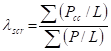
where
P = member axial force from the factored load analysis, with tension taken as negative
L = column length and the summation includes all columns within a storey.
Source: http://www.buildnova.com/buildnovav3/IS800/IS800SECTION4.doc
Web site to visit: http://www.buildnova.com
Author of the text: indicated on the source document of the above text
If you are the author of the text above and you not agree to share your knowledge for teaching, research, scholarship (for fair use as indicated in the United States copyrigh low) please send us an e-mail and we will remove your text quickly. Fair use is a limitation and exception to the exclusive right granted by copyright law to the author of a creative work. In United States copyright law, fair use is a doctrine that permits limited use of copyrighted material without acquiring permission from the rights holders. Examples of fair use include commentary, search engines, criticism, news reporting, research, teaching, library archiving and scholarship. It provides for the legal, unlicensed citation or incorporation of copyrighted material in another author's work under a four-factor balancing test. (source: http://en.wikipedia.org/wiki/Fair_use)
The information of medicine and health contained in the site are of a general nature and purpose which is purely informative and for this reason may not replace in any case, the council of a doctor or a qualified entity legally to the profession.
The texts are the property of their respective authors and we thank them for giving us the opportunity to share for free to students, teachers and users of the Web their texts will used only for illustrative educational and scientific purposes only.
All the information in our site are given for nonprofit educational purposes