Non-Circular Ducts:
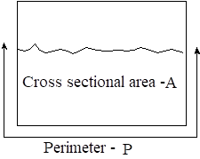
For flow in non-circular ducts or ducts for which the flow does not fill the entire cross-section, we can define the hydraulic diameter Dh as
 where A = cross-sectional area of actual flow, P = wetted perimeter, i.e. the perimeter on which viscous shear acts |
|
With this definition, all previous equations for the Reynolds number, Re, friction factor, f, and head loss, hf , are valid as previously defined and can be used on both circular and non-circular flow cross-sections.
Minor Losses
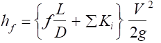
In addition to frictional losses for a length L of pipe, we must also consider losses due to various fittings (valves, unions, elbows, tees, etc.). These losses are typically expressed as
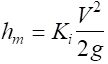
where
hm = the equivalent head loss across the fitting or flow component
V = average flow velocity for the pipe size of the fitting
Ki = the minor loss coefficient for given flow component; valve, union, etc.
See Sec. 6.7, Table 6.5, 6.6, Fig. 6.19, 6.20, 6.21, 6.22, etc.
i.e. Loss Coefficient 
Table 6.5 shows minor loss K values for several common types of valves, fully open, and for elbows and tees.
Figure 6.18 shows minor loss K values for several types of common valves.
Note that the K valves shown here are for the indicated fractional opening. Also, the fully open values may not be consistent with values indicated in Table 6.5 for fully open valves or for the valve of a particular manufacturer. In general, use specific manufacturer’s data when available.
Note that exit losses are K @ 1 for all submerged exits, e.g. fluid discharged into a tank at a level below the fluid surface. Also, for an open pipe discharge to the atmosphere, there is no loss coefficient when the energy equation is written only to the end of the pipe. In general, do not take point 1 for an analysis to be in the plane of an inlet having an inlet loss. You do not know what fraction of the inlet loss to consider. |
|
|
Note that the losses shown in Fig. 6.22 do not represent losses associated with pipe unions or reducers. These must be found in other sources in the literature. Also note that the loss coefficient is always based on the velocity in the smaller diameter (d) of the pipe, irrespective of the direction of flow. Assume that this is also true for reducers and similar area change fittings. |
These and other sources of data now provide the ability to determine frictional losses for both the pipe and other piping/duct flow components.
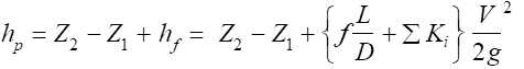
The total frictional loss now becomes
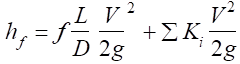
or
These equations would be appropriate for a single pipe size (with average velocity V). For multiple pipe/duct sizes, this term must be repeated for each pipe size.
Key Point: The energy equation must still be used to determine the total
head loss and pressure drop from all possible contributions.
Example 6.16
Water, r = 1.94 slugs/ft3 and n = 1.1 E-5 ft2/s, is pumped between two reservoirs at 0.2 ft3/s through 400 ft of 2–in diameter pipe with e/D = 0.001 having the indicated minor losses. Compute the pump horsepower (motor size) required.
Writing the energy equation between points 1 and 2 (the free surfaces of the two reservoirs), we obtain
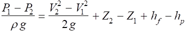
For this problem, the pressure (P1 = P2) and velocity (V1 = V2 = 0) head terms are zero and the equation reduces to
For a flow rate Q = 0.2 ft3/s we obtain

With e/D = 0.001 and 
The flow is turbulent and Haaland’s equation can be used to determine the friction factor:

Note: The loss for a pipe bend is not the same as for an elbow fitting. If there were no tank at the pipe discharge and point 2 were at the pipe exit, there would be no exit loss coefficient. However, there would be an exit K.E. term. |
|
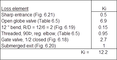
The minor losses for the problem are summarized in the following table:
Substituting in the energy equation we obtain
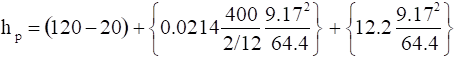
![]()
Note the distribution of the total loss between static, pipe friction, and minor losses.
The power required to be delivered to the fluid is given by


If the pump has an efficiency of 70%, the power requirements would be specified by

Solution Summary:
To solve a basic pipe flow pressure drop problem, use the following procedure:
Multiple-Pipe Systems
Basic concepts of pipe system analysis apply also to multiple pipe systems. However, the solution procedure is more involved and can be iterative.
Consider the following:
a. Multiple pipes in series
b. Multiple pipes in parallel
Series Pipe System:
The indicated pipe system has a steady flow rate Q through three pipes with diameters D1, D2, & D3. Two important rules apply to this problem. |
|
1. The flow rate is the same through each pipe section. For incompressible flow, this is expressed as
Q1 = Q2 = Q3 = Q or D12V1 = D22V2 = D32V3
2. The total frictional head loss is the sum of the head losses through the various sections.
![]()

Note: Be careful how you evaluate the transitions from one section to the next. In general, loss coefficients for transition sections are based on the velocity of the smaller section.
Example: Given a pipe system as shown in the previous figure. The total pressure drop is Pa – Pb = 150 kPa and the elevation change is Zb – Za = – 5 m. Given the following data, determine the flow rate of water through the section.

The energy equation is written as |
|
Since the flow rate Q and velocity are the only remaining variables, the solution is easily obtained from a spreadsheet by assuming Q until DP = 150 kPa.
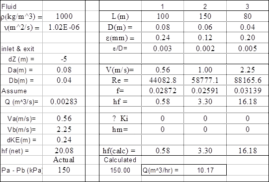
Thus it is seen that a flow rate of 10.17 m3/hr produces the indicated head loss through each section and a net total DP = 150 kPa.
A solution can also be obtained by writing all terms explicitly in terms of a single velocity, however, the algebra is quite complex (unless the flow is laminar), and an iterative solution is still required. All equations used to obtain the solution are the same as those presented in previous sections.
Parallel Pipe Systems
A flow rate QT enters the indicated parallel pipe system. The total flow splits and flows through 3 parallel pipe sections, each with different diameters and lengths. Two basic rules apply to parallel pipe systems: |
|
1. The total flow entering the parallel section is equal to the sum of the flow rates through the individual sections
2. The total pressure drop across the parallel section is equal to the pressure drop across each individual parallel segment.
Note that if a common junction is used for the start and end of the parallel section, the velocity and elevation change is also the same for each section. Thus, the flow rate through each section must be such that the frictional loss is the same for each and the sum of the flow rates equals the total flow.
For the special case of no kinetic or potential energy change across the sections, we obtain:
ht = ( hf + hm)1 = ( hf + hm)2 =( hf + hm)3
and
QT = Q1 + Q2 + Q3
Again, the equation used for both the pipe friction and minor losses is the same as previously presented. The flow and pipe dimensions used for the previous example are now applied to the parallel circuit shown above.
Example: A parallel pipe section consists of three parallel pipe segments with the lengths and diameters shown below. The total pressure drop is 150 kPa and the parallel section has an elevation drop of 5 m. Neglecting minor losses and kinetic energy changes, determine the flow rate of water through each pipe section.
The solution is iterative and is again presented in a spreadsheet. The net friction head loss of 20.3 m now occurs across each of the three parallel sections.

The strong effect of diameter can be seen with the smallest diameter having the lowest flow rate, even though it also has the shortest length of pipe.
Again the total flow is distributed between the three parallel sections such that the head loss across each section is the same, in this case 20.3 m.
Bernoulli Obstruction Theory
An obstruction meter is a device that is used to measure flow rate using the pressure drop caused by an obstruction in the flow. Given a basic obstruction meter as shown in the accompanying figure, write Bernoulli’s equation between points 1 & 2.
|
|
Assume:
1. Steady - flow 2. incompressible flow 3. no friction losses
4. uniform velocity profiles at 1 & 2 5. Z1 = Z2
For these conditions, Bernoulli’s Equation and conservation of mass become:
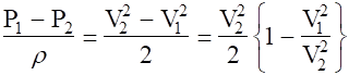

Substituting and solving for V2, we obtain:
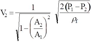
The volumetric flow rate is now given by

The above equation predicts the flow for ideal (frictionless) flow conditions.
Define: Cd = discharge or flow coefficient
![]()
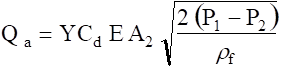
Can now write the equation for the actual flow rate as:

Define: E = Velocity of approach factor
 where
where
![]() = ratio of the throat-minimum flow diameter to the main flow diameter
= ratio of the throat-minimum flow diameter to the main flow diameter
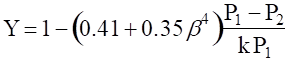
Also: define Y = expansion factor = factor which accounts for compressibility effects of the flow ( usually small). Y = 1 no compressibility effects, Y < 1, some compressibility effects.
Therefore, the final equation now becomes:
or:
![]()
For gases, the Expansion Factor, Y, is given by the expression:
Orifice Flow Rate Analysis
We will now outline the procedure required to use a given thin plate orifice to determine the flow rate based on orifice geometry and measured pressure drop. Data: D, b, d, P1g, DP, T1, Pbar 1. Calculate orifice constants: g, At, E g (fluid), At = p d2/4, |
|
2. If fluid is a gas, calculate the Expansion factor, Y. Otherwise, set Y = 1.
![]()
![]()
3. Calculate the Discharge Coefficient
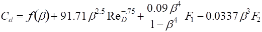
where
![]()
The factors F1 and F2 vary with pressure tap position.
corner taps: F1 = 0 F2 = 0
D & 1/2 D taps: F1 = 0.4333 F2 = 0.47
Flange taps:  D > 2.3 in
2.0 ≤ D ≤2.3 in ![]()
4. Calculate Mass Flow Rate
![]()
Where for ideal gases: r = P1/RT1
5. Calculate the actual volumetric flow rate

Source: http://www.eng.auburn.edu/~tplacek/courses/2610/samba/CHEN2610FacultyCh6b.doc
Web site to visit: http://www.eng.auburn.edu/
Author of the text: indicated on the source document of the above text
If you are the author of the text above and you not agree to share your knowledge for teaching, research, scholarship (for fair use as indicated in the United States copyrigh low) please send us an e-mail and we will remove your text quickly. Fair use is a limitation and exception to the exclusive right granted by copyright law to the author of a creative work. In United States copyright law, fair use is a doctrine that permits limited use of copyrighted material without acquiring permission from the rights holders. Examples of fair use include commentary, search engines, criticism, news reporting, research, teaching, library archiving and scholarship. It provides for the legal, unlicensed citation or incorporation of copyrighted material in another author's work under a four-factor balancing test. (source: http://en.wikipedia.org/wiki/Fair_use)
The information of medicine and health contained in the site are of a general nature and purpose which is purely informative and for this reason may not replace in any case, the council of a doctor or a qualified entity legally to the profession.
The texts are the property of their respective authors and we thank them for giving us the opportunity to share for free to students, teachers and users of the Web their texts will used only for illustrative educational and scientific purposes only.
All the information in our site are given for nonprofit educational purposes