The subject, "Pipe Supports" is a much more complex subject than the term suggests. There are so many situations that a pipe can find itself in and in every case it will need to be supported. Pipe supports are subdivided into two main categories:
The primary pipe supports systems are those supports that are a part of the infrastructure and fall under the prime responsibility of the civil and structural department. The secondary pipe support systems are more a part of the piping systems and as such fall under the prime responsibility of the mechanical piping contractor. While the prime responsibilities are divided there must be a cross over of responsibility to ensure co-ordination between the civil and mechanical disciplines to ensure the overall system design works.
Figure 1 – Section through building showing primary and secondary supports
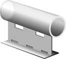
Primary pipe supports systems are also be referred to as pipe racks, pipe ways, pipe alleys. These support systems may be major or minor and they may be overhead or sleeper pipe racks. It is important to understand that even though they are called pipe racks they support and carry more than just piping. These other items may include the cables for electrical and instrumentation services.
Overhead pipe racks (see figure 1 below) are elevated to the point where you can walk and/or drive under the supported piping. Sleepers or sleeper ways are low to the ground so there is no passage under the supported piping. Figure 3 below shows a pre-fabricated pipe rack being pre-loaded in a pipefitting workshop before installation to reduce time on site.
Figure 2 – Intersection of elevated pipe racks
When designing pipe racks many factors need to be considered such as:
Figure 3 – Pre-fabricated and pre-loaded pipe racks prepared in a workshop
Secondary pipe supports cover a wide range of devices which can be sub divided into two categories:
Engineered pipe supports relates to devices that are non-static, one-of-a-kind, location and condition specific. They are identified at the time the need is recognized and then designed and engineered for that specific need. They can incorporate springs, and/or dampers to compensate for thermal expansion or contraction, or to provide vibration isolation, shock control, or vibration excitation of the pipe due to earthquake motion. These are designed and selected by the piping stress engineer and piping designer to ensure that the complete piping system functions correctly
Miscellaneous pipe support refers to a broad array of devices that includes items such as Anchors, Base Supports, Cradles, Dummy Support Legs, Guides, Hanger Rods, Pick-ups, Shoes, etc. Many different suppliers have different versions of these devices and client companies may opt to allow each pipe designer to select the most appropriate device or more commonly they will have a pre-engineered solution standardized to cover many similar type situations. Having pre-engineered solutions, saves money, reduces stock holding, provides consistency of design, results in a safer design and makes installation easier in the field as pipe fitters develop a consistent method of installation.
Table 1 below gives a list of names for typical secondary supports what they are used for and their frequency of use during normal operations. Table 2 gives images of secondary pipe supports and their common names.
Name |
Purpose |
Frequency |
Anchors |
Prevent the movement of the pipe line normally in a pipe rack |
High |
Base Anchors |
Prevent any movement of a piping assembly normally at grade |
Low |
Base Guides |
Allows only vertical movement (up or down) of piping assemblies at grade |
Low |
Base Supports |
Provides support under piping assemblies normally at grade |
High |
Cradles |
Provides protection for cold insulation when crossings a pipe support in pipe racks |
High for cold service |
Directional Anchor |
Restricts the movement of a pipe line to a specific direction pipe racks |
High |
Dummy Support Legs |
Provides added length to a pipeline for the purpose of support. Not restricted to only pipe rack usage |
High |
Field Supports |
A catchall term sometimes used by a piping designer that includes any type of non-infrastructure support. These items are not location specific. |
High |
Guides |
Provides restraint to keep a pipe line in place in horizontal pipe racks or vertical pipe racks in buildings or up tall equipment |
High |
Gussets |
Provides added reinforcement for small (fragile) branch connections on a larger header or pipe |
See note #1 |
Hanger Rods |
A wide verity of top-down pipe supports situations, not location specific. |
High |
Hold Downs |
Prevents or controls mechanical vibration in piping systems. |
See note #2 |
Load Distribution Pads |
Provides additional mass for thin wall pipe at a point of concentrated stress loading. This item is not location specific. |
Low |
Pick-ups |
Provides support of pipes from other pipes or overhead beams and is not location specific. |
Moderate |
Shoes |
Provides "mini-supports for lines with hot insulation normally only used only at pipe support points |
High |
Trunnions |
Provides load-carrying points for vertical pipelines most often used to support pipes attached to tall vertical vessels or hung from tall structures. |
Low |
Table 1 – Secondary supports, purpose and frequency of use
  |
|
|
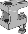
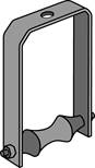
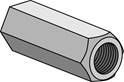
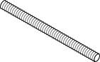
Threaded rod & coupling |
Beam Clamp |
Steel Pipe hanger |
|
|
|
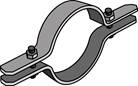
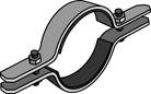
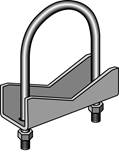
Standard pipe clamp |
Rubber lined pipe clamp |
Pipe clamp with threaded rod connector |
|
|
|
Pipe roller chair |
Pipe roller hanger |
Anchor chair with u-bolt |
|
|
|
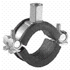
T pipe anchor |
T pipe anchor with pipe clamps |
PTFE hold down slide plate |
Table 2 – Illustrations of common secondary supports and their names
As there are many different manufacturers and suppliers of secondary pipe supports it is not possible to provide specific installation instructions for secondary supports; however the following points should be observed for good piping installation practices.
It is important to verify that actual bracketing requirements are in accordance with client specifications, piping codes applicable to the project and are supervised and signed off by relevant personnel.
In general, the table 3 shows the requirements for minimum rod sizes and maximum spacing, for different pipe sizes unless otherwise indicated on the piping drawings or client specific support requirements.
Nominal Pipe Size (") |
Max Span (m) |
Min Rod Size (mm) |
<1 |
2 |
8 |
1 to 1 1/4 |
2 |
10 |
1 1/2 |
2.7 |
10 |
2 |
3 |
10 |
3 |
3.6 |
12 |
4 |
4.2 |
16 |
6 |
5.1 |
20 |
8 |
5.8 |
20 |
10 |
6.7 |
20 |
12 |
7 |
25 |
Table 3 – Maximum spacing and threaded rod size for different pipe sizes
In addition to the above requirements the following points are recommended:
When installing and supporting equipment it is best refer to specific manufactures instructions for positioning and securing equipment. The following points should be observed.
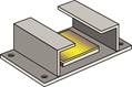
As piping is installed at ambient temperature, any piping carrying hot or cold fluids will expand or contract when it reaches its operating temperature. The expansion especially in length can create stresses at welded joints or upon certain areas of the piping distribution system. Piping systems designers must assess piping runs and identify where the natural flexibility of the pipe and fittings can absorb the stresses of thermal expansion and where design intervention is required. The following are some possible solutions for Cold draw: The pipe is pre-stressed (as in figure 4) in the opposite direction at ambient temperature (i.e. by tightening at a flange joint) so that when the system is heated the pipe expands and the stress is removed.

Figure 4 – Cold draw where pipe is pre-stressed at ambient installation
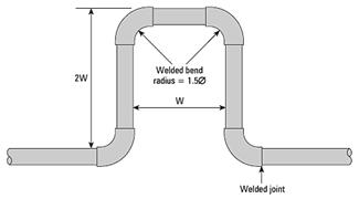
Expansion loops as seen in figure 5 below can be used on horizontal long runs of pipework and can be fabricated elbows and straight lengths of pipe. The expansion that these types of loops can allow for can be read from the table in figure 6.
Figure 5 – Expansion Loop for long straight runs of pipework
Source: http://local.ecollege.ie/Content/APPRENTICE/liu/pipefitting/word/M4_U4_Bracket%20Fabrication.doc
Web site to visit: http://local.ecollege.ie
Author of the text: indicated on the source document of the above text
If you are the author of the text above and you not agree to share your knowledge for teaching, research, scholarship (for fair use as indicated in the United States copyrigh low) please send us an e-mail and we will remove your text quickly. Fair use is a limitation and exception to the exclusive right granted by copyright law to the author of a creative work. In United States copyright law, fair use is a doctrine that permits limited use of copyrighted material without acquiring permission from the rights holders. Examples of fair use include commentary, search engines, criticism, news reporting, research, teaching, library archiving and scholarship. It provides for the legal, unlicensed citation or incorporation of copyrighted material in another author's work under a four-factor balancing test. (source: http://en.wikipedia.org/wiki/Fair_use)
The information of medicine and health contained in the site are of a general nature and purpose which is purely informative and for this reason may not replace in any case, the council of a doctor or a qualified entity legally to the profession.
The texts are the property of their respective authors and we thank them for giving us the opportunity to share for free to students, teachers and users of the Web their texts will used only for illustrative educational and scientific purposes only.
All the information in our site are given for nonprofit educational purposes