
Pneumatic Logic Sensors and Actuators
Pneumatic control system is frequently used in building automatic assembly machines. Pneumatic sensors and actuators are used in such control system. Electric current flows between logic sensors and actuators during machine control sequence. In other hands, pressure airline flows between pneumatic sensors and actuators during machine control sequence. In most cases, both control systems are used to build the machine control sequence. Although, hydraulic control system can also be used, this will not be considered in current Chapter.
The main structure of the limit valves, push button and emergency stop valves are the same. Pneumatic limit valves are the equivalent of mechanical limit switches. Furthermore, the pneumatic push button and emergency stop valves are equivalent of mechanical push button and emergency stop mechanical switches. The main difference between the pneumatic limit valves and the mechanical switches, in the latter, the actuating arm or plunger shifts a so-called directional-control valve rather than electric contacts. Same thing is applied for push button and emergency valves.

For example, consider Fig. 6.1, which shows a so-called 3/2 limit valve (meaning 3 connections and 2 positions valve). The valve shown as normally closed, so that the outlet line is exhausted to atmosphere when the valve is not actuated. When the valve is actuated, the roller is depressed against the return spring at the bottom, so that the valve opens and passes supply pressure to the outlet line.
Fig. 6.2 illustrates another pneumatic limit valve called 5/2 limit valve (meaning 5 connections and 2 positions valve), which has two independent outlet lines, one is normally open and is the second normally closed. Such a valve is analogous to limit mechanical switch with changeover contacts (NO and NC contacts switch).
For both cases, the limit valve can be used as push-button valve and do the same stated functions, as shown in Fig. 6.2.
Most directional-control valves are of the spool and sleeve type. Fig. 6.3, shows a 5/2 spool valve (schematically). When the spool position or pilot line has been pressurized by p1 line. Flow line between A & D ports, and B & E posts are passed, while C is blocked. If pilot line p2 is pressurized, the spool shifted to the lift with corresponding change in flow paths as illustrated in Fig 6.3. Also, Fig. 6.3 shows also the ISO or ANSI standard symbol of 5/2 way directional valve. This type of directional valve can be used as SET-REST mechanical memory in pneumatic circuit.

The main difference between the solenoid actuation directional control valve and pilot control valve, is the way of displacement of the valve spool. Spool valve displacement is carried out using two pressurized air p1 and p2 in case of the pilot control valve. While solenoid and spring mechanisms are used to displace the spool valve in case of the solenoid actuation directional valve (or simply solenoid directional valve) as shown in Fig. 6.4. Similarly, solenoid actuation can also be used with 3/2 ways directional valve.

These pneumatic valves that discussed so far called directional control valves and used as ON/OFF valves to control the airflow to the actuators. Most directional-control valves have two or three discrete ports or positions. Fig. 6.5, shows the international ISO or United States ANSI standard symbols for three connections two position valve, 3/2 valve. The two rectangles represent the two discrete positions of the valve. Since the connection tubes are drawn in this case attached to the left rectangle, this means that the valve is presently in the left position.
In Fig. 6.5, there are three connections, or valve ports, labeled as A, B and C, respectively. As long as the valve remains in the left position, left rectangle, there is airflow from port A to C, while port B is blocked. When this valve is shifted to its right position, right rectangle, port A blocked, while port B and C are connected. The arrowheads shown on the symbol are optional, they indicating the airflow directions.
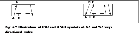
Fig. 6.5, shows the symbol of a five connections two position (5/2) valve. In the left position, port A and D are connected, and likewise port B and E, while port C is blocked. In the right position, port A is blocked, while port B is connected to D, and port C to E.
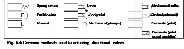
In addition to the rectangles showing the valve positions, the symbol must also indicate how the valve is shifted or actuated. The symbols for common actuation methods shown in Fig. 6.6. As illustrated in Fig 6.6, the actuation symbols are for only one valve position. Actually, the opposite actuation must also exist, because otherwise the valve could never shifted back to its original position. various combination are available. For example, Fig( 6.7a) shows a valve with pilot-pressure actuation and return spring. In Fig 6.7(b, a) solenoid is substituted for the pilot line. Fig 6.7(c & d), no return spring, instead the valve is shifted back by activating the opposite pilot line or solenoid, respectively.
Fig 6.7(e) shows additional position to the 5/2 directional valve. The mid-position blocks all the ports. This type of valves is called 5/3 directional valves (5 connections, 3 positions). The original position (or normal position) of the valve at the middle (blocked ports position).
Fig. 6.8, shows some additional pneumatic symbols, and most should be self-explanatory. For example, air supply symbol used as common (all points connected to air supply). Check valve symbol represents a one-direction air flow valve. The shuttle valve has free-float ball or disk able to seal either of two seats, if either input A or B is pressurized, the ball seals the opposite seat, hence output C is high (this type of valve used as OR gate, where the C output is high only when one of the input A or B high).


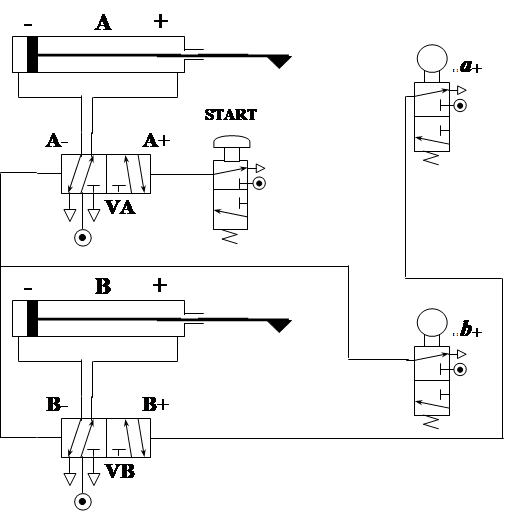
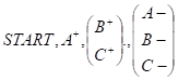
Operation :

Operation :

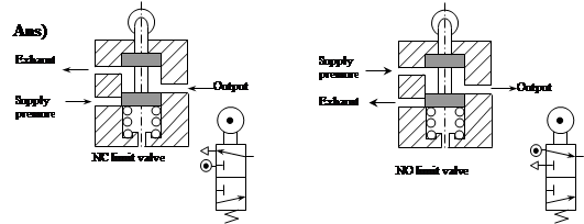
Ans)

Source: http://faculty.ksu.edu.sa/AliAlsamhan/Manufacturing%20Automation%20Using%20PLC/chapter_6_ver3.doc
Web site to visit: http://faculty.ksu.edu.sa/
Author of the text: indicated on the source document of the above text
If you are the author of the text above and you not agree to share your knowledge for teaching, research, scholarship (for fair use as indicated in the United States copyrigh low) please send us an e-mail and we will remove your text quickly. Fair use is a limitation and exception to the exclusive right granted by copyright law to the author of a creative work. In United States copyright law, fair use is a doctrine that permits limited use of copyrighted material without acquiring permission from the rights holders. Examples of fair use include commentary, search engines, criticism, news reporting, research, teaching, library archiving and scholarship. It provides for the legal, unlicensed citation or incorporation of copyrighted material in another author's work under a four-factor balancing test. (source: http://en.wikipedia.org/wiki/Fair_use)
The information of medicine and health contained in the site are of a general nature and purpose which is purely informative and for this reason may not replace in any case, the council of a doctor or a qualified entity legally to the profession.
The texts are the property of their respective authors and we thank them for giving us the opportunity to share for free to students, teachers and users of the Web their texts will used only for illustrative educational and scientific purposes only.
All the information in our site are given for nonprofit educational purposes