
The reactor generates excess power because of the inefficiencies in converting the core’s thermal power into electricity. The goal of the radiator group was to design a lightweight radiator that would dissipate the excess power from the MSR operating on either the Lunar or Martian surface. This section will step through the process of choosing the radiator design and then present a detailed analysis of the chosen radiator.
First, there is an overview of the specific requirements, based on our proposed mission and the objectives agreed upon by the entire design team. Next is an examination of the different radiator concepts that the group considered, with analysis of the important facets of each. The radiator group used decision methodology to determine the concepts that it would use in the design; the third section breaks down this decision making process and explains the results. Based on the conclusions of the concept analysis, the fourth section describes the design the group chose and explores its important aspects. The following section contains a summary of the analyses and calculations that the group performed in order to select and verify various parameters of the design. Finally, the sixth section will discuss ideas for future work.
From the overall MSR design goals (see Section X.X), the radiator group created a set of more specific requirements. These requirements pertain to how the radiator interacts with the other systems and the environment. From the systems side, consider how the radiator fits into the sequence of events from launch to surface operation; first, it must fit into the launch vehicle along with the other reactor components. This means that not only must there be sufficient contiguous volume, but also the weight of the radiator, when added to the weight of the rest of the reactor, must not exceed the available launch capacity. This requirement necessitates give and take between the various design groups to arrive at the optimal parameters. Second, the radiator must be able to withstand the large g-forces and vibrations associated with launch and landing without damaging itself or neighboring components. Third, the radiator must be in a configuration where it operates correctly after landing. Whether or not there is unpacking required after the lander positions the reactor, the radiator must be able to mate with the other systems and operate when the startup command is given. This dictates consideration of the linkages between the radiator and the other components and its role in the reactor startup procedure.
Using the same sequence of events, the design team generated the environmental requirements. It is likely the radiator will contact the Earth’s atmosphere when it is first constructed and packaged into the rocket. The design must ensure that the high atmospheric pressure (compared to its destinations) does not damage any components, and chemicals present in the air do not corrode or contaminated its surfaces. Next, during the rocket’s transit from Earth to either the Moon or Mars, the radiator will experience a low-gravity environment and be subject to direct radiation from the sun. Once the radiator lands on the surface the design must take into consideration the effects of gravity, temperatures in the range of 100-400 K and material reactivity with the atmosphere and soil. In addition, since the radiator will begin to operate, it is important to asses how operation interacts with the planetary environment.
With only the design goals and constraints given above, this is still a very open design question. The design team tailored the scope of the radiator design to a manageable set of design considerations. Here we will describe what design aspects the team specifically investigated, and which merit further analysis.
Integration of the radiator with the other systems is critical in the creation of an overall tenable design for the MSR. To this end, the radiator group worked closely with the power conversion group, which in turn collaborated with the core group, to ensure that the three systems interfaced appropriately, and to verify that the choices made by the radiator team met the entire design team’s requirements. Communication with the other groups was important for balancing mass and size issues, and creating a geometry that complimented the rest of the system. However, since the design of the lander and all the physical requirements of the assembly are beyond the scope of this investigation, this group did not consider exact methods of attachment and construction.
The environment is also a critical factor in our design since the peculiarities of the Martian and Lunar surface conditions control the effectiveness of a radiator. The design group brought the major environmental factors into consideration by taking into account the physical conditions on the Lunar and Martian surfaces, including meteorological conditions, temperature swings and chemical composition of the atmosphere and soil. See Appendix X for a detailed discussion of the Martian and Lunar environments. In particular, the design team evaluated the important chemical interactions that could occur on exposed surfaces. Since it is beyond the scope of this project to determine the landing sites for the reactor, in general the group used average planetary conditions when doing these analyses.
In order to gauge the efficacy of our design choices, the radiator group performed analyses to calculate the interactions between the radiator and the other systems, as well as interactions within the radiator system itself. Thermal transfer analyses are important for gauging the operational efficiency of the system, and ensuring components perform as predicted. In addition, the radiator group performed calculations validating the mechanical structure, taking into account the physical stresses imposed by the other systems and the environment. For this investigation most of these analyses considered steady-state thermo-physical conditions to reduce the computational load.
The purpose of this design project is to deliver a physical design, but not one exacting enough to permit construction. For example, it is beyond the scope of the team’s analyses to determine exact methods of assembly, selection of parts, or electromechanical operation. Given that such technology is possible, and the design is logical and meets all the other requirements, the design team left these finer details of structure for future consideration. Finally, although the design groups have based choices on technology that is currently available, the researchers acknowledge that there are manufacturing, testing and qualification timelines that are important but difficult to predict. If this system were included on a NASA launch, there would be important deadlines and budgetary concerns that would impose additional requirements. While the decision methodology used in this project has tried to consider these restrictions, it is also beyond the scope of this project to fit the design into a specific development window.
Before beginning major design work, the radiator subgroup researched past heat rejection systems in order to take advantage of the experience already gained in this field. Previous work on space power has given these concepts serious consideration; they represent a valuable compilation of technical solutions to the many challenges of practical radiator design. These concepts included design for both interplanetary and surface operations, and the design team considered both because of the sparse atmospheric conditions on the Moon and Mars. This section explains and tabulates the important points of function, materials and operating parameters for each of the seven heat rejection concepts the group investigated. The radiator subgroup used this information to determine the optimum starting concepts for the Martian and Lunar surface radiators, from which our MSR design ultimately evolved.
A recent reactor system envisioned by NASA was a high-temperature fusion powered spacecraft that utilized partial power conversion; some of the energy created by the reactor generates electricity while the rest powers the propulsion system or radiates into space as waste heat. The heat rejection system uses gaseous helium pumped through two separate but parallel loops to transport heat from the reactor to large panel radiators [3].
The center of the power generation system is a 7900 MWth fusion reactor. Of this energy, 6685 MWth powers the craft’s magnetic propulsion system or is lost to space. About 100 MW of the remaining 1215 MWth powers the craft’s Brayton cycle power conversion system and generates 29 MWe. The 100 MW of thermal energy is carried from the reactor by a high-pressure helium loop to a turbine, and then to a low-temperature radiator measuring 10000 m2. The helium temperature is 1700 K at the core outlet and 1000 K after the turbine. The coolant experiences a 500 K temperature drop across the radiator, and flows through a compressor in-line with the turbine before returning to the reactor.
A separate low-pressure Helium flow carries the other 1115 MWth directly to a 4070 m2 high-temperature radiator at 1700 K. This coolant loop experiences a 700 K drop across the radiator and flows back into the fusion core via a motor-driven compressor pump. See Figure 1.2‑1 for the layout of the reactor systems.
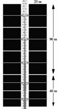
Figure 1.2‑2: The layout of the helium-fed radiator panels. The helium flows through pipes in the central truss, and then out and back across the ends of the panels of heat pipes (shown in black) [3].
Table 1.2‑1: Properties of the Helium-based heat rejection system.
Radiated Power |
1186 MWth |
|
Radiator Inlet Temperature |
high-temperature radiator |
1700 K |
low-temperature radiator |
1000 K |
|
Radiator Area |
high-temperature radiator |
4070 m2 |
low-temperature radiator |
10000 m2 |
|
Primary Coolant |
Gaseous Helium |
|
Heat Pipes |
Carbon-Carbon composite with Lithium or Sodium-Potassium fluid |
|
Structure |
Carbon-Carbon composites, refractory metals, high-temperature ceramics |
|
Linearly Scaled Radiator Mass for Rejecting 900 kWth |
1 MT |
|
The low-temperature radiator is composed of Carbon-Carbon heat pipes with sodium-potassium eutectic coolant. The helium flows over the evaporator section of the heat pipes, and the condensing end of the heat pipes attach to high-emissivity fins for radiating the energy into space. The piping and supports for the radiator system are made of refractory metal alloys such as aluminum and zirconium oxides and ceramics like SiC and Si3N4. The high-temperature radiator uses a similar design, except that the heat pipe working fluid is lithium, and most of the radiator’s superstructure is composed of Carbon-Carbon composites. In both radiators, zones separate the heat pipes in order to maximize temperature and thus efficiency. Table 1.2‑1 is a summary of the properties of the helium-fed radiator.
This design has several very good attributes, namely that it operates at high temperatures and radiates a very large amount of power. Because the working fluid is a light gas the radiator panels are much less massive than liquid metal systems. The drawbacks of this system are the weight and complexity of its auxiliary components (compressor/pump, high-pressure piping) and the lack of inherent redundancy (although the radiator area does include a safety factor of 1.2). The primary source of cooling is though the forced-flow high-temperature loop, which requires a high output electric powered pump. The dependency on electrical power and the mechanical complications of a motorized high-rpm component present reliability issues when considered for use in a remote 5-year life reactor system. In addition, the helium coolant will be at high pressure, which only increases the problems of leaks and introduces a single-point failure mode for the system.
It would not be difficult to scale down this system to 900 kWth, with the helium circulating through a heat exchanger to recover heat from the PCU, although the auxiliary components (pump and heat exchanger) would dominate the mass. The helium would flow through a smaller version of the low-temperature radiator with the same heat pipe construction. An electric pump would then force the gas back into the heat exchanger to repeat the cycle. The pressures and flow rates in this system would need to be kept high to provide adequate cooling.
The Systems for Nuclear Auxiliary Power (SNAP) projects resulted in the development of multiple fission reactor and radioisotope thermal generator designs for space use [19]. The goal of the SNAP-2 program was development of a nuclear auxiliary power unit capable of generating 3 kWe for one year with a total weight less than 340 kg [6]. See the layout of the reactor, power conversion unit and radiator systems
The SNAP-2 reactor utilizes a sodium-potassium eutectic (NaK) coolant to heat a secondary Mercury loop that is the working fluid for a Rankine power conversion cycle. The reactor produces 50 kWth that the PCU utilizes to generate electricity. After passing through the turbine at 894 K, the radiator cools and condenses the gaseous Mercury at 589 K. An integral subcooler in series with the radiator then reduces the liquid Mercury temperature to 489 K before it returns to the Hg-NaK heat exchanger. The radiator is a hollow cone-shaped surface with the reactor shield truncating the tip, and the PCU located at the base. The radiator is 2.87 m long with a diameter of 0.76 m at the tip of the cone and 1.52 m at the base, giving an effective radiator area of 10.2 m2.
Table 1.2‑2: Properties of the SNAP-2 radiator-condenser.
Radiated Power |
47 kWth |
Radiator Inlet Temperature (condenser and subcooler) |
600 K |
Radiator Area |
10.2 m2 |
Radiator Mass |
51.7 kg |
Radiator Coolant |
Hg |
Structure |
Steel pipes with an Aluminum shell |
Linearly Scaled Radiator Mass for Rejecting 900 kWth |
1.5 MT |
The radiator-condenser is made of steel tubes arrayed beneath an Aluminum shell 0.5 mm in thickness. The inside of the tubes are an eccentric shape, with the inner diameter offset, so that additional steel is located at the steel-aluminum interface for protection against micro-meteor penetration. The tubes have an inner diameter of 6.9 mm and an outer diameter of 9.3 mm. The dry weight of the radiator (tubes and shell) is 51.7 kg. Table 1.2‑2 contains a summary of the radiator’s properties.
The SNAP-2 radiator design is interesting because it takes advantage of the condensing fluid to maintain a constant temperature over most of the radiating surface, similar to a heat pipe. The radiator is also a very low weight given the amount of power radiated, with a power-to-mass ratio of 0.139 kW/kg. The two drawbacks of the system are the need to provide pumping for the coolant and single-point failure characteristics. Mercury is the working fluid for the Rankine power conversion unit as well as the radiator coolant, and therefore the two systems share the mass penalty for pumping a dense fluid; however, it comes at the mass benefit of not having a secondary heat exchanger. However, in a system where the coolant is not part of the PCU cycle a heat exchanger introduces significant complexity. In addition, a failure in any one of the radiator pipes will cause a rapid depressurization of the system and loss of cooling for the reactor. In order to reduce this possibility the design requires additional armor. Also, Mercury is toxic, and in the case of a launch accident, or leak of mercury on Martian surface, it poses a hazard both to human health and the local environment.
This concept might provide an acceptable size for this project, assuming the size and mass scale linearly with power level. Scaled up to a rejection power of 900 kWth, this system would require a pump to circulate the coolant through a heat exchanger and out to the radiator. The major drawback is the greater pressure drop across the radiator, since radiator area will scale upwards with the power.
The SNAP-10A is the only fission reactor launched and operated in space by the United States. Placed into orbit on April 3, 1965, the SNAP-10A operated for 43 days before shutting down due to an electrical malfunction in the orbital booster [6]. The SNAP-10A design called for continuous operation for at least one year, operation without moving parts (although initial startup uses rotating control drums), consistent operation independent of its position with respect to the Sun or Earth, the ability to withstand the forces of launch and spaceflight, and presentation of a minimal hazard during launch and orbit [19]. Figure 1.2‑4 is a drawing of the SNAP-10A launch system.
Figure 1.2‑4: The SNAP-10A launch vehicle in an exploded view, with the reactor and radiator assembly denoted as the NPU. The radiator is composed of the 40 parallel aluminum strips that run axially from the tip of the cone. The Agena is the orbital booster that maneuvered the reactor into final position after its separation from the Atlas launch vehicle [6].
The SNAP-10A reactor produced 43 kWth with a core similar to the SNAP-2 design. Liquid metal circulated through the core and into 40 tubes running axially below the reactor vessel. Thermoelectric generators mounted against these tubes absorbed the thermal energy by conduction. The radiator plates then attached directly to the outside end of the thermoelectric converters and emitted the excess heat into space. Figure 1.2‑5 depicts the layout of the radiator and power conversion system.
Figure 1.2‑5: A schematic view of a SNAP-10A coolant tube with the thermoelectric pills and radiator strips [6].
The NaK coolant for the SNAP-10A circulated through the coolant tubes with the aid of an electromagnetic pump. The NaK left the reactor with a temperature of 833 K and reentered at 761 K. Thermocouples attached between the tubes and the radiator supplied the pump’s electrical power. Seventy-two germanium-silicon thermoelectric generator pills were spaced along each coolant tube and held in place with tungsten shoes. The wiring separates the generators on each tube into three electrical modules, each with 24 generators; each module had an electrical output between four and five watts. The total power output from the thermoelectric system was about 500 We. Welded to the outside end of the thermoelectric pellets are the radiator panels. The panels are made of thin aluminum strips with an emissivity of approximately 0.9. Small gaps placed between the strips maintain their electrical isolation, and they keep the cold end of the thermoelectric pills at approximately 611 K. Table 1.2‑3 is a summary of the SNAP-10A radiator properties.
Table 1.2‑3: Properties of the SNAP-10A radiator.
Radiated Power |
42.5 kWth |
Radiator Temperature |
611 K |
Radiator Area |
6 m2 |
Radiator Mass |
340 kg |
Radiator Structure |
Aluminum strips welded to cold end of thermoelectric pellets |
Linearly Scaled Radiator Mass for Rejecting 900 kWth |
7 MT |
The SNAP-10A design is significantly lower power than our goal; however, it is instructive overall because it is the only completely flight-proven fission reactor system available. The system’s main weakness is the continuous NaK loop, which presents many opportunities for a single-point failure because it covers the entire radiator area. One advantage of this design is that the radiator does not require unfolding or setup once on the surface, removing the need for moving components or flexibility.
A version of this design rejecting 900 kWth is similar to the SNAP-2 but without the need to condense the coolant; the use of an electromagnetic pump rather than a compressor or fan further simplifies the operation. The downside is that this design would be too heavy at this power level- around 7 MT. Because the SNAP-10A was actually constructed and operated in space, this mass prediction is more believable than the much lower estimate (1.5 MT) given by the SNAP-2 designers.
A Liquid Droplet Radiator (LDR) creates a flowing mist of fine droplets between an emitter and the collector in space [2]. The idea is the very large surface area of the mist (the sum of the surface area of each droplet) will promote radiative energy loss to space while the actual mass of the mist is significantly less than a solid plate radiator and working fluid. To minimize thermal radiation re-absorption, the generator maintains the mist at approximately a millimeter in thickness. Although not tested in space or with a high-power application, there have been extensive studies of the LDR since the 1950’s [8].
The LDR system consists of five main components: the liquid reservoir, pumps, heat exchanger, droplet generator and droplet collector. The radiator functions by first drawing heat through the heat exchanger into the working fluid, either a silicon-based oil or a liquid metal. It is necessary to use these types of fluids because their low vapor pressures will minimize losses during the droplet transmission; however, these fluids are also undesirable for use in most thermodynamic cycles and therefore an intermediate heat exchanger between the PCU and the radiator loop is generally necessary. Next, pipes carry the fluid to the droplet generator, which creates the droplets and forms them into a thin, rectangular, directed mist. This mist travels through space over a distance up to several hundred meters. The collector is located directly across from the droplet generator. It absorbs the droplets and returns the liquid to the closed piping system where pumps return the cooled fluid to the heat exchanger. See Figure 1.2‑6 for a schematic layout of the LDR, and Table 1.2‑4 for a summary of the radiator’s properties.
The most common liquid metal coolant for this design is NaK, although for lower power applications the silicon oils FC75 and DC705 are preferred. The high-temperature coolant contacts almost half of the components in the system, meaning they will need to be made of either refractory metals or high-temperature composites like Carbon-Carbon. Metals such as aluminum make up the lower temperature components.
Table 1.2‑4: Properties of the liquid droplet radiator.
Radiated Power (optimum range) |
5-50 kWth |
Radiator Inlet Temperature (optimum) |
400 K or less |
Radiator Area |
On the order of 100 m2 per generator, one is needed two reject 50 kW |
Primary Coolant |
NaK or silicon-based oil |
Mechanical Components |
Regulating valves, electrical pumps, and droplet generator |
Structure |
Carbon-Carbon composites, refractory metals, Aluminum |
The major benefit of this design is the ability to create radiator area out of empty space; thereby realizing significant mass savings compared to the tube/panel type radiators. Given sufficient efficiency in the droplet generator and integrity of the overall structure, it is possible to create an extremely long radiator length in zero gravity. The presence of microgravity on Mars and the Moon presents major problems then, because the droplet stream will face serious deformation after a few meters. Certainly, on Mars, where the atmosphere and wind are not negligible, utilizing an open heat rejection system is of questionable feasibility from both an operations viewpoint and an environment protection viewpoint. Although the radiator coolant is not from the primary system, it still could release activation products into the environment because it is still in close proximity of the reactor. In fact, even during normal operation in space there are significant evaporative losses in the system, requiring a large reservoir of coolant for online replenishing. The mechanical and electrical complexity and needs of the system are also a negative factor when you consider the operation of pumps, valves, and the droplet generator for five years. Finally, while this design is scalable from the size examined in the literature, it is only mass-competitive with heat pipe systems in the 400 K or less operating range due to evaporative losses. The ideal system would have an inlet-side temperature of 320 K at the heat exchanger with a total system radiated power of up to 50 kWth.
A Liquid Sheet Radiator (LSR) radiator is very similar to the LDR system except that a very thin layer of liquid replaces the mist of radiating droplets [8]. An LSR works by exposing a planar liquid sheet of sub-millimeter thickness to space; a film fluid emerges at a set speed from the injection slot of the generator, creating a liquid sheet in space. A collector recovers the fluid and re-circulates it by means of a system of pipes and pumps. The liquid then enters an intermediate heat exchanger in order to take up the waste heat from the power cycle fluid [2]. See Figure 1.2‑7 for a schematic of the LSR.
The main components of the LSR are the sheet generator, collector, intermediate heat exchanger and circulation pump. The generator vessel must be large enough to blunt any pressure oscillations and the sheet generation precise enough to ensure uniform fluid velocity over the entire length of the injection slot.
The characteristic element of an LSR is the fluid sheet. Since the fluid used in the radiator has to operate in an extremely low-pressure environment, it must possess a very low vapor pressure in order to minimize evaporative losses. The liquid metals, such as NaK, generally present better features than silicone fluids. Liquid metals have higher thermal conductivities and lower viscosities (by up to an order of magnitude). In addition, due to the fluid dynamics governing sheet formation, there is a limited distance over which the sheet may deployed. The sheet starts as a plane but converges into a cone of fluid after about ten meters if it starts with an initial (optimum) width of approximately one meter. See Table 1.2‑5 for a summary of the properties of the LSR radiator.
Table 1.2‑5: Summary of the properties of the Liquid Sheet Radiator.
Radiated Power (optimum range) |
5-50 kWth |
Radiator inlet temperature (optimum) |
400 K or less |
Radiator area |
10 m2 per generator, at least ten required to reject 50 kW |
Primary Coolant |
NaK or silicon-based oil |
Mechanical Components |
Regulating valves, electrical pumps, and sheet generator |
Structure |
Carbon-Carbon composites, refractory metals, Aluminum |
This is another radiator concept that is innovative in many aspects of its design. However, the LSR's main component, the liquid sheet, makes the system very complicated since it requires a pump and generator. Like the LDR this system also has an ideal operating temperature around 400 K corresponding to a radiated power of around 50 kW. At higher temperatures, the coolant evaporation rate increases, and therefore the LSR would require a very large volume of make-up fluid. An added complication is the limited length of the sheet. To increase the power radiated without going to unacceptably high temperatures, it is necessary to put multiple generator/collector pairs in series or parallel, greatly increasing the size and mass of the system. Finally, the sheet configuration is less efficient at radiating than the liquid droplet mist, and therefore the sheet system would be much more massive than a comparable LDR device.
The Safe Affordable Fission Engine (SAFE) bridges the gap between low-power radioisotope systems and the high-power fission systems envisioned for future spaceflight. The SAFE-400 reactor provides an output of 400 kWth for up to 10 years. The reactor deposits energy into gas flow via two independent heat pipe-to-gas heat exchangers; this gas then feeds two independent Brayton power cycles producing 100 kWe total power [1][11][13]. See Figure 1.2‑8 for a schematic layout of the SAFE-400 power conversion system.
Each heat pipe-to-gas heat exchanger is composed of an array of the condensing end of the core heat pipes, which transfer their thermal energy to the gas. The working fluid for the heat pipes is sodium, and the pipe’s shell is made of a Carbon-Carbon composite with a Niobium-1%-Zirconium liner. The heat exchanger inlet and outlet temperatures are 900 K and 1150 K, respectively, and the working fluid is Helium-28%-Xenon.
The SAFE-400’s radiator uses heat pipes as well. The working fluid for these heat pipes is sodium-iodine (NaI), and the pipes are made of a Carbon-Carbon composite with inner liners made of Nb-1%-Zr. The radiator panels are a Carbon-Carbon composite sandwich design, with plates mounted on either side of the heat pipes. The specific mass of this radiator is only 1.6 kg/m2, operating with a power generation cycle outlet temperature of 510 K; the design calls for a total radiator area of 150 m2. See Figure 1.2‑9 for a schematic of the radiator, and Table 1.2‑6 for a summary of its properties.
Table 1.2‑6: Properties of the SAFE-400 radiator.
Radiated Power |
400 kWth |
Radiator Inlet Temperature |
510 K |
Radiator Area |
150 m2 |
Primary Coolant |
He-Xe |
Heat Pipes |
Carbon-Carbon composite with Nb-1%-Zr liner with NaI fluid |
Structure |
Carbon-Carbon composite sandwich design with plates on either side of the heat pipes |
Linearly Scaled Radiator Mass for Rejecting 900 kWth |
3 MT |
The power dissipated is in the range of our design requirements, and the projected size of the radiator area is reasonable. Redundant heat pipes passively cool the reactor, which is an added safety advantage; therefore, the reactor does not require a hermitically sealed vessel or any components that are required by a pumped loop system. The biggest plus for this concept is the overall simplicity of operation [16][20].
The SP-100 is a liquid metal cooled reactor rated to produce 550 kWe. The design calls for 7 years of operation with a survival probability of 0.99. This design concept considered the reactor as the central power source for a lunar research settlement, utilizing either a Brayton or Stirling power conversion cycle [15].
For the Brayton system, liquid metal coolant flows from the core and through a liquid-to-gas heat exchanger, which passes the thermal energy to the gas. This gas flows directly into a recuperated Brayton power conversion system to produce electricity. Four panel radiators unfold perpendicular to the surface from the reactor assembly to reject the waste heat to space as thermal radiation. For the Stirling system, the difference is the primary heat exchanger becomes liquid-to-liquid, and then the secondary liquid coolant heats the Stirling engines.
For the Brayton system, lithium is the coolant used in the core, and is pumped to the first heat exchanger that transfers heat to the power cycle working fluid, Helium-Xenon. The He-Xe gas passes through four independent Brayton engines to produce electricity. A gas-to-liquid cooler then transfers the waste heat to a second liquid metal loop. This rejection loop contains sodium-potassium eutectic that flows to the radiator, which consists of a series of heat pipes. See Figure 1.2‑10 for an overview of the Brayton power conversion system.
The reactor produces 2.4 MWth, and at the reactor outlet is liquid Lithium at a temperature of 1355 K. This flows through the first heat exchanger where it transfers its heat to the new working fluid, He-Xe, at a temperature of 1300 K. The He-Xe fluid passes through the Brayton turbine and recuperator, reaching the cooler at a temperature of 640 K. The Brayton engine produces 582 kWe. The He-Xe then passes through the cooler, yielding NaK with an output temperature of 631 K. The NaK enters the radiator system at 631K flowing into four manifolds, one through each of the radiator arms. The thermal energy from the NaK heats the evaporating end of heat pipes in twelve radiating panels; there is 2.3 MWth of total heat rejection at an average temperature of 471 K. The NaK exits the radiator with a temperature of 397 K, and an electromagnetic pump then sends it back to the cooler for reheating.
The radiator is composed of 12 panels arranged in four radial arrays; each array is a radiator section of 233 Carbon-Carbon heat pipes. Of the total heat pipe inventory, 922 use H2O and 10 use Mercury as the working fluid. The radiator panels fold in for launch, and then extend outward for operation once the reactor is in place on the lunar surface; this movement requires a drive system and flexible connections for the NaK piping. The heat pipes are vertically oriented to emit radiation from both sides, weigh about 4460 kg altogether, and are 565 m2 in total area. The radiator assembly, including the panel support structure, weighs 4960 kg. See Figure 1.2‑11 for a schematic layout of the Brayton core and radiator system, and Table 1.2‑7 for a summary of the radiator parameters.
Table 1.2‑7: Design parameters for the SP-100 based lunar radiator utilizing Brayton cycle power conversion.
Radiated Power |
1.8 MWth |
Radiator Inlet Temperature |
631 K |
Radiator Average Temperature |
471 K |
Radiator Area |
565 m2 |
Radiator Mass |
4960 kg |
Radiator Coolant |
NaK |
Heat Pipes |
932 Carbon-Carbon composite heat pipes (922 with H2O fluid and 10 with Hg fluid) |
Structure |
12 Carbon-Carbon heat pipe panels oriented vertically in four arrays from the reactor assembly. Coolant flows through a baffle heating evaporator end of heat pipes. |
Linearly Scaled Radiator Mass for Rejecting 900 kWth |
2.4 MT |
The Stirling system is similar to the Brayton, but there are important differences in some areas; see Figure 1.2‑12 for a schematic of the Sterling power conversion system. First, the reactor operates with a lower power, only 1.89 MWth. The primary heat exchanger takes Lithium from the core at 1355 K and transfers the heat to a second Lithium loop, outputting liquid Lithium at 1304 K. This loop passes the heat to the four independent Stirling engines, which produce 596 kWe. The NaK coolant loop exits the Stirling engine at 625 K and enters the radiator manifolds. The Stirling’s radiator uses only 415 heat pipes, giving an overall area of 185 m2 to radiate 1.29 MWth. On each arm there are about 73 H2O and 30 Hg fluid heat pipes with Carbon-Carbon composite shells. These heat pipes are also vertically oriented and radiate at an average temperature of 576 K with a total mass of 1675 kg; the radiator assembly, including support structure, weighs 2025 kg. See Figure 10 for a schematic layout of the Sterling core and radiator systems, and Table 1.2‑8 for a summary of the parameters of the radiator.
The overall design for this reactor is useful given the objectives of this project. The power levels and temperatures are in useful ranges so the materials choices should be similar. This model has an expectant life of 7 years and with only 11 of the 12 panels operating the radiator will still function normally. The vertical orientation of the radiator panels is an interesting design choice; it allows for heat rejection from both sides of the panels, but increases the amount of solar energy absorbed by the radiators. The double-sided design also means the panels will receive radiation from direct heating and reflection off planetary surfaces.
After researching seven major past radiator concepts, the radiator group applied the appropriate decision methodology to all of the concepts. See Section X.X for details about the development of the design team’s decision methodology. The concept with the highest overall ranking, the SP-100, was therefore determined to be the optimum starting point from which the radiator subgroup could evolve our own design. The SAFE-400 concept also ranked close to the SP-100 and very highly compared to the others; these two concepts use similar components and design methodologies. The radiator group’s conceptual design therefore utilizes the thin Carbon-Carbon panel radiators with embedded Carbon-Carbon heat pipes found in both concepts. The heat pipes transport the waste energy beneath the panels, which conduct the heat away, and then radiate it into space.
The seven radiator concepts under consideration were first evaluated using five litmus test criteria: safety, 100 kWe, 5 EFPY, works on the Moon and Mars, and obeys environmental regulations for the appropriate extraterrestrial environments. If a concept fails to satisfy one or more of these criteria then it will not be subject to further analysis or consideration for use in this project.
After an evaluation of the seven concepts, only two failed to satisfy all of these criteria: the liquid droplet radiator (LDR) and the liquid sheet radiator (LSR). These are similar designs that suffer from the same basic deficiencies. In order to meet the requirements for 100kWe for 5 years, both the area and mass of these systems become prohibitive. The theoretical liquid droplet radiator, considered the more efficient but physically more difficult of the two designs, has a rating of around 170Wth/kg, equating to a mass of over 5MT for the MSR system. In addition, this mass estimate only takes into consideration the active components; it does not account for the fluid reservoir, which LDR needs to make up for evaporative losses from the droplets. Therefore the mass might as much as double when considering an operating temperature of around 1000K [2][8].
Another critical issue for the liquid droplet and liquid sheet designs are their ability to operate on the Moon and Mars. While they are ideal for work in space, the presence of even small amounts of gravity and atmospheric gasses, particles, and wind would make their operation much less efficient, less predictable and less reliable. Contamination of the system by foreign substances and accelerated loss of the liquid stream during the radiation segment are major problems. Coupled with this are the environmental considerations, as the LDR and LSR are operating in what is essentially an open system. In even the most efficient design, significant coolant losses are expected, and therefore this coolant (either a silicon-based oil or liquid metal) will be contaminating the local atmosphere and soil.
Because of the difficulties in meeting the criteria of radiating 900kWth, functioning for 5 years, working on the Moon and Mars and satisfying environmental regulations, the radiator group will not consider the liquid droplet and liquid sheet radiators any further. While they are promising designs for the future, they require significantly more research and testing in order to sufficiently quantify their physical properties and allow development of models to predict accurately their performance and operational limitations on the surface of the Moon and Mars.
The radiator group ranked the five remaining radiator concepts based on eleven extent-to-which criteria divided between four main categories: small mass and size, controllability, launchability, and reliability/low-maintenance. See Table 1.3‑1 below for a listing of the criteria and the concept rankings.
The radiator group ranked the concepts one through five, with five denoting that the design fulfills the criterion better than the other four concepts. A lower score indicates that the concept does not fulfill the criterion as well as another concept, not that it necessarily fails to fulfill the criterion at all. This is important, since this means that a concept could receive the lowest score in a category but still meet and exceed our design requirements in that category.
Table 1.3‑1: Extent-to-Which rankings for the five radiator concepts that passed the litmus tests.
|
SP-100 |
SAFE-400 |
SNAP-2 |
SNAP-10A |
Helium fed |
Small Mass and Size - 1.35 |
|||||
Radiator mass is small |
4 |
3 |
2 |
1 |
5 |
Peripheral systems mass are small |
4 |
4 |
3 |
5 |
1 |
Radiating area is small |
3 |
1 |
2 |
4 |
5 |
Controllable - 1.14 |
|||||
Minimal setup |
4 |
4 |
2 |
1 |
5 |
Minimal operational control |
5 |
5 |
2 |
3 |
1 |
Launchable/Accident Safe - 1.13 |
|||||
Not mechanically fragile |
4 |
4 |
3 |
5 |
1 |
Not chemically hazardous |
4 |
4 |
1 |
2 |
5 |
High Reliability and Limited Maintenance - 1.00 |
|||||
Few single point failures |
5 |
5 |
1 |
1 |
1 |
Few moving parts |
5 |
5 |
3 |
4 |
1 |
Limited maintenance |
5 |
5 |
1 |
1 |
1 |
Proven technology |
4 |
4 |
2 |
5 |
1 |
Total (of 62.95 possible) |
53.15 |
49.1 |
25.53 |
36.97 |
32.47 |
Under the small mass and size category, the radiator mass was evaluated based on the mass per kilowatt of power radiated. Similarly, the group based the comparison of radiator areas on area per kilowatt of power radiated. This method of ranking allows a fair comparison of all the concepts even though the power levels and output temperatures specified in our previous analyses were not all equivalent, assuming they scale linearly. This linear scaling is reasonable because the system temperatures are the same, and therefore the calculation only changes rate of energy generation. Power and area are in one-to-one correlation in the radiative heat transfer equation and thus scale with each other when the other variables (such as temperature) are constant. The group recognizes that there are properties that vary based on temperature and materials choices, and that we can adjust some temperatures and materials while staying within the same overall design concept.
Peripheral systems mass and size refers to items besides the radiating surface and its supports. It relates directly to whether any other devices such as pumps, reservoirs or heat exchangers are required, and how massive such items are when compared to components for the other conceptual systems.
The group defined the two items under the controllability category by the guiding principal that radiator deployment and control should be as simple as possible. The need to thaw coolant, mechanically extend the panels and regulate pressures and flows are all examples of the types of controllability issues used to evaluate the various concepts. Setup refers to actions that would need to taken by controllers or performed automatically after launch but before reactor operation. Operational control refers to any manipulation that would need to occur, again either by operators or automatically, in the course of normal system operation over the five-year life.
The group placed fragility and potential chemical hazard under launchability because the launch subjects the radiator to tremendous physical stress, and a launch failure should not present an excessive hazard to the environment. One of the main parts of the pre-flight testing of a component that will be launched into space is vibration testing. With this in mind, the weakest points of any design are likely to be moving and mechanical connections such as rotating parts, joints, seals, bolts and welds. The chemical hazard comes into play in the event there is a rupture of a part of the radiator assembly during takeoff, flight or initial orbit. In such an event, any toxic or reactive chemicals should not enter the atmosphere or disperse in large quantities. All these concepts pass the safety and environment litmus tests because they will not cause a large environmental impact. However, it is still important to differentiate on a relative scale the impact of, say sodium versus helium release. A helium leak would quickly deplete the system’s helium inventory, but helium is inert. A punctured heat pipe would release a small volume of sodium, but it will react with water and produce hydrogen gas, which will burn in an oxygen environment. Liquid mercury, in contrast, will not react violently with the environment but is a toxic hazard to humans and wildlife [6][19].
The reliability and maintenance criteria cover operation of the radiator system once it is in place on the planetary surface. Single point failures present a major problem for reliability because it alerts us that any breach or puncture in one component would render the entire system useless. The next criterion under reliability is moving parts, since they will cause wear and are a principle malfunction and failure risk. While any need for maintenance during any phase of the mission is undesirable and the group’s design seeks to avoid it, if there is a need to perform maintenance and is possible, it is important to asses how readily it could be accomplished. The maintenance criterion takes into account the modularity and accessibility of the components in the radiator system and answers the question: how easy are most maintenance tasks? This covers replacement of major components (and depends on how many auxiliary components exist) as well as patching and other in-place repairs to the entire system. Finally, proven technology is a plus for our design because it gives us an idea of the reliability and of the experience engineers have with the technologies involved in each concept. The highest rankings here suggest the components have well-characterized behavior and have been flight-tested and operated in an extraterrestrial environment.
The SP-100 lunar radiator concept received the highest overall ranking in the ETW test evaluation, followed closely by the SAFE-400. It ranked highest among the concepts in mass and size, controllability and maintenance, and second in launchability. The heat pipes, which are central to its design, are also its biggest benefit: they are a proven technology that provides redundancy and passive operation. Even if a heat pipe is punctured or otherwise malfunctions, it does not impede the function of its neighbors. So long as there is sufficient leeway in operating parameters, neighboring heat pipes will be able to dissipate the excess heat imparted by a pipe failure. They are passive because they do not require any active control and do not dynamically interface with other systems. Only the dimensions and temperature differences at the ends of the heat pipes dictate the fluid flow; there are no valves, regulators or moving parts. Because the heat pipes do not rely on any auxiliary components, and the failure of a few heat pipes will not fail the system, this concept is also inherently low-maintenance [15].
The SP-100 concept received its lowest ranks in radiator size and chemical hazard. The power radiated per unit area was not as high as other concepts such as the Helium-fed or SNAP-10A; however, it was not significantly worse when considering the radiating temperature. At high temperature the radiative efficiency increases considerably, which is one of the reasons the Helium-fed system had such good characteristics. Increasing the average radiating temperature is much easier in a heat pipe system because they are isothermal over a large part of their length, and thus increasing their temperature in order to radiate efficiently in the 900kWth range will greatly improve the power per unit area.
A chemical hazard is generally inherent when using heat pipes, and is a result of the liquid metal working fluid. While not present in very large amounts, in the event of a failure during launch, leading to the rupture of heat pipes in the terrestrial environment, there is the possibility of fire or toxic contamination over a small area. This is a shortcoming of all the heat pipe systems evaluated, and therefore the group ranked them lower than the helium system since helium is an inert gas. However, heat pipe systems are significantly better than a system that pumps a large volume of liquid metal through a loop configuration [19].
The SAFE-400 also received high rankings and in the end measured up well to the SP-100 design, and much better than the next best concept. Indeed, the SAFE-400 is similar in form to the SP-100 since both used a working fluid to transfer waste energy to an array of heat pipes. Therefore, the designs received similar marks regarding mass, safety, control and reliability. The area per unit of power radiated of the SAFE-400 design is slightly greater than the SP-100 mainly because of its lower operating temperature [11][16].
The SP-100 radiator concept passed all five of the litmus test criteria and received the highest overall ranking on the ETW criteria covering the various critical elements concerning our design project. The categories where it received its lowest rankings reflect items to note about this concept, but not significant problems or obstacles to obtaining a launchable design. Therefore, when making our final design choices and parameter selections the radiator group will use the SP-100 design as the primary reference concept. For the purposes of this project it embodies the best of the past space-based radiator work relevant to the MSR system and thus provides an excellent starting point for our own design. Since the SAFE-400 is a similar design and ranked very highly compared to the other concepts under consideration, we will also use it as a foundation from which to choose our other radiator components. This does not mean that the design team will use the specifications of these two designs exclusive of other ideas or without innovation. By starting with a preexisting concept the radiator design team is able create an evolutionary design that gives due consideration to the extensive previous work by experts in this field.
Both the SP-100 and SAFE-400 utilize a finned heat pipe array to dissipate energy to space, and the MSR’s radiator design will also use this fundamental concept. The fins of each heat pipe connect to create a single continuous panel, and the panels will have a sandwiched design, meaning that the heat pipes are located beneath or between the panels and must conduct all their heat to a surrounding sheath that is a part of the fin. Both the outer shell of the heat pipes and the fins will be a Carbon-Carbon composite, chosen for its low density, excellent strength, high thermal conductivity and high emissivity. The fin composite needs a high thermal conductivity and emissivity so that heat spreads out evenly from the heat pipes and radiates efficiently into space. Figure 1.3‑1 below shows a schematic of this radiator panel concept.
Other aspects of the SP-100 and SAFE-400 designs, such as the orientation of the panels, supports, working fluids and heat exchanger construction are more system-specific. The next section discusses the selection of these characteristics for the MSR, along with improvements to the original design, and provides the final design of the MSR radiator.
Based on the MSR project’s goals, operational constraints and the radiator technologies discussed in the previous sections, the radiator group designed a thermal radiator. The basic concept is a heat-pipe based radiator similar to the SP-100 and SAFE-400 designs discussed in Section 1.2. This section discusses the design considerations and explains the choices that the group made. It also details the final design, a finned heat pipe radiator, and reviews the physical parameters.
As an integral part of the MSR system, the radiator has several requirements that it must fulfill. The goals of the project dictate some of these constraints, and the design choices of other groups influence others.
The radiator group worked to integrate the design with the other MSR systems. The design must meet the specific radiator requirements while also allowing the other groups to meet their needs. The most obvious interaction is between the radiator and the power conversion system. The 127 core heat pipes exit vertically from the bottom of the reactor vessel and enter thermionic sleeves, which are just over 1cm in diameter and 60cm in length. The radiator system will require a heat exchanger to interface with these sleeves and transport the energy to the heat pipes, while minimizing temperature drop in order to maximize efficiency.
Because the thermionic conversion system is only 10% efficient in generation and there will be additional losses in transmission, in order to generate 100kWe the reactor produces 1.25MWth. Consequently, the radiator has to be able to dispose of 900kWth of excess heat. The radiator must provide this heat removal from the outside of the thermionic sleeves, and ensure they maintain their design temperature of 950K, in order to ensure proper power output.
The ultimate energy removal mechanism is radiation, and therefore the rate of heat dissipation is:
![]() (1.4-1)
(1.4-1)
Where ![]() is the power radiated,
is the power radiated, ![]() is the Stefan-Boltzmann constant and T∞ is the apparent temperature of the environment [12]. The properties of the surface are the emissivity,
is the Stefan-Boltzmann constant and T∞ is the apparent temperature of the environment [12]. The properties of the surface are the emissivity, ![]() , the radiator area A, and the temperature of the surface Ts. It is apparent from Equ341 that temperature is the controlling factor in the efficiency of the radiator. Since the power level is set, in order to minimize the size of the radiator it is important to use a high-emissivity material for the fins, and to keep the fins at as high a temperature as possible.
, the radiator area A, and the temperature of the surface Ts. It is apparent from Equ341 that temperature is the controlling factor in the efficiency of the radiator. Since the power level is set, in order to minimize the size of the radiator it is important to use a high-emissivity material for the fins, and to keep the fins at as high a temperature as possible.
The radiator must also be able to operate at full power for five years. Because the heat pipes are a sealed loop and operate passively, their performance should not degrade over this time. The radiator has no other mechanical or electrical systems that operate after its initial startup. This passive operation also maintains the systems safety- even a break in a heat pipe would release only very a small amount of fluid and vapor to the environment, and does not compromise the safety of other systems. The thermal radiation emitted by the panels is non-ionizing radiation in the infrared and visible spectrum, so there is no danger of radiation damage. Furthermore, the panels direct the energy away from the other MSR components and the surface to prevent overheating.
Because the project objectives call for the use of the same MSR design for the Moon and Mars, the radiator must be versatile enough to handle the attributes of both environments. See Section X.X for a discussion of the geophysical and meteorological properties of the Moon and Mars. On the Moon, there is no atmosphere, which allows the apparent temperature of the sky to be near 0 K, while it is around 300 K on Mars. However, the Moon is much closer to the Sun than Mars, so the incident solar energy is double, on average it is 1360 and 590 W/m2, respectively.
Finally, the radiator must accommodate the MSR launch mass limitation of 10MT. Based on the expected masses of the other MSR components, the radiator group decided on an upper bound of 2MT. In addition, as discussed above, the size of the launch vehicle payload area is a 5m tall cylinder, with a diameter of 5m. The reactor module, as well as the shielding and thermionic converters, occupies a cylinder 1.19m in radius at about 1m tall. These dimensions give a large amount of room around and above the rest of the components to situate the radiator panels.
The design team separated the MSR radiator design into several sections. First is the structure of the PCU interface, panels and physical supports. Next are the operational components concerned with control, monitoring and dust removal. Finally this section will discuss the major chemical reaction of concern, oxidation.
PCU Interface
In conjunction with the PCU group, the radiator group decided on annular heat pipes as the most effective method of transferring heat from the thermionic sleeves to the radiator. See Section X.X for a description of the PCU to radiator heat exchanger. After the 60cm annular length, the heat pipe contracts down to a normal pipe, 2cm in diameter with the same wall thickness. This diameter allows the central vapor channel to retain approximately the same cross-sectional flow area between the two segments.
The major differences in design between the core and radiator heat pipes are the shell material and working fluid. The Carbon-Carbon shell has a high melting point (3650 K) typical of ceramics, with a thermal conductivity (66 W/m K) comparable to a metal. This combination avoids the danger of softening or deformation without introducing a large thermal resistance [5]. See Appendix X for a tabulation of the materials the design group considered, and their relevant properties.
The design group chose potassium as the heat pipe working fluid for its excellent thermal properties and low density compared to other liquid metals. Among the fluids the group investigated, potassium’s melting point, 1032 K at STP, is the closest to the radiator input temperature of 950 K. By decreasing the ambient pressure inside the heat pipe to 39.8kPa, roughly one-third atmospheric pressure on Earth, the boiling point reduces to 940 K.
Radiator Panel
After the annular section, the heat pipes make a 90º bend with a 0.5m radius of curvature. The pipes are arranged so that they emerge equally spaced around the circumference of the core, and extend outwards horizontally to a maximum radius of 2.4m from the centerline. The pipes make another bend before reaching the horizontal limit and angle back towards the reactor at 52º from the ground. After exiting the bend, a Carbon-Carbon fin encases each heat pipe; these fins connect between all of the pipes to form a conical sheet. To improve conduction between the pipes and the fins, the design has the heat pipes inset 3mm into grooves on the front side of the sheet, and a 5mm thick sleeve encases each pipe and is contiguous with the panel. The conical radiator surface alone is 2.34m in height and 4.58m wide at the base. The heat pipes and paneling end at distance of 46cm from the centerline of the craft, giving a total surface area of 41.5m2. Figure 1.4‑1 below shows a cross section of the panel design, and Figure 1.4‑2 is a cross section of the entire assembly.
The radiator assembly has a total height of 3.34m and a diameter of 4.8m yielding an average heat pipe length of 6m. The conical shape with pipes on the outside maximizes radiator area as well as angle from the ground. As the angle of the radiator panels becomes steeper, the amount of incident solar radiation decreases, because there is diminishing contribution due to reflection from planetary surfaces. The outside surface of the radiator panel is polished to achieve an emissivity near 0.9, while the inside surface is roughened or coated to minimize the emissivity. Lowering the inside emissivity reduces the amount of thermal radiation directed back at the other reactor components. The radiator group modeled the radiator as a grey body and therefore its emissivity is equal to its radiative absorptivity, which is the fraction of incident radiation a material absorbs versus the amount it reflects. Reducing this factor on the inside surface limits absorption of thermal radiation emanating directly from the core. The total mass of the panel is 360kg, while the heat pipes, with potassium fluid, are about 155kg.
Supports
The finned heat pipe concept offers excellent thermal transfer characteristics, but in order to maximize the temperature across the fin surface it is important to make the fin as thin as possible. Likewise, to decrease the thermal resistance between the heat pipe fluid and the fin, the group designed the heat pipe’s shell to be as thin as possible. This necessitates the inclusion of a separate structure to support the weight of the radiator and secure it to the rest of the MSR assembly.
A titanium frame spans the inside surface of the conical surface to provide support to the panel and the heat pipes. The choice of titanium alloy would maximize strength in the high temperature range, but in general, titanium’s melting point is well above 1800 K. This frame mounts at a central point above the reactor to prevent interference with shield movement. Eight beams, each 2cm in diameter, start from a central hub at an angle of 6.54º, and intersect the panels at their midpoint 1.5m from the reactor centerline. Each of these main supports connects to a titanium spreader bar, which attaches to three rectangular titanium strips running along the inside surface of the conical panel. These strips form three equally spaced rings, and support the weight of both the panel and the heat pipes. The spreader bars are 1.25m long and 1cm in diameter, while the strips have a height of 4cm and a thickness of 5mm. Figure 1.4‑3 below shows a cross section of the radiator support frame and the location of the support rings. The total mass of the support structure is 50kg.
The titanium frame distributes the mass of the radiator to the same structural assembly supporting the reactor, which in turn connects to the landing vehicle. Because of the low weight of the panels, the geometry of the radiator cone will not raise the MSR’s center of mass appreciably. Therefore, this design assumes the lander will already have sufficient stability to prevent the MSR assembly from swaying or tipping.
Operation
One of the major advantages of using heat pipes is their passive operation. Each pipe is independent of the others and is a completely sealed loop without pumps, valves or junctions. This simplifies their design and improves reliability. The SP-100 design does incorporate mechanical operation, however. Because of the large size of its heat pipe radiators, the panels are stored folded against the reactor until it is in place on the surface. Such a range of motion would require motors and joints to allow the panels to unfold, heating to thaw the working fluid in the heat pipes, and a supplementary electrical system to provide the needed power before activation of the reactor.
This design requires no folding or unfolding system, which greatly simplifies construction and eliminates the need for any mechanical controls. However, the liquid metal working fluid will be solid before reactor startup and therefore requires thawing. The reactor could accomplish thawing by slowly increasing core power and allowing conduction through the heat pipes to melt the fluid. However, in the event this process is too slow or unreliable, it is desirable to have a system to heat the pipes directly and independently of core power. The thawing system consists of wire heating elements wrapped around the lower exposed pipe runs. Activated on command just before reactor startup, a battery runs a small current through the wires, warming the solid potassium and accelerating the thawing process once the core becomes hot. Thermocouples attached to exterior of the heat pipes and panels at various locations will provide temperature data to ensure the thawing is proceeding as expected. In addition, these probes will provide important data on the long-term operational characteristics of the radiator system.
Once operating the heat pipes do not require any outside manipulation, as long as the appropriate thermal conditions exist at the two ends, heat will be absorbed in the evaporator section and transported naturally to the condenser region. Like with the SP-100, however, the initial startup may require activation of the un-packaging sequence and operation of heaters and motors. This might require an uplink to human controllers, but an onboard computer should be able to perform the same tasks. To monitor this operation the design should include diagnostic instrumentation installed at different points in the radiator. Monitoring may also be required for verification or study of the operational performance of the radiator. The design team would need to integrate such a system into the radiator without interfering with its operation, and transmit the data back to a central processor on the MSR lander.
Dust Removal
A fine layer of dust covers the surface of both the Moon and Mars. This dust could be stirred up into the atmosphere by activity (such as landing and unpacking) and by the wind on Mars. Because the radiator will have a large surface area exposed to the atmosphere, it is likely that this dust will settle out on its panels. Dust buildup tends to degrade the radiator’s performance by decreasing the fin’s effective emissivity, however this effect varies based on materials and temperature. A dust removal system will mitigate this problem by either removing the dust from the surface or preventing its accumulation [9][4].
Several studies have shown that Carbon-Carbon exhibits a minimal emissivity penalty due to dust buildup of micrometer thicknesses [10][4]. This thickness of buildup is very difficult to prevent, although on Mars the wind will likely prevent large amounts of accumulation on the inclined panels by blowing it off. However, models have predicted more significant dust buildup on the Moon, especially due to multiple launches and landings over a five-year multi-mission period. Every time a spacecraft lands or takes off from the surface, rocket thrust will blow soil around and the resulting dust could drift towards the radiator. This dust buildup tends to improve emissivity initially, but after five years, the performance may drop by five percent. The best strategy for preventing this degradation is to limit the amount of activity near the reactor, especially those that might stir up large amounts of soil. In addition, the radiator must have sufficient surface area to withstand the expected 5% loss of emissivity over operating lifetime. See Figure 1.4‑4 for the required radiator area based on effective panel emissivity.
Oxidation
The main drawback to the use of Carbon-Carbon composites is the potential for oxidation at temperatures above 600 K. Chemical oxidation occurs when oxygen diffuses into the composite matrix and combines with the carbon atoms, forming CO and CO2 gasses. Although oxygen is present as oxides in the soil of the Moon and Mars and in the Martian atmosphere, the lack of atomic oxygen will reduce the oxidation rate considerably. To forestall any further degradation of the radiator’s surfaces or the heat pipes, the design team decided to treat all exposed Carbon-Carbon surfaces with a silicon carbide coating. This coating will react with oxygen and create an inert layer SiO2. Both SiC and SiO2 have thermal conductivities similar to Carbon-Carbon, and the presence of the coating should not decrease the emissivity of the panels appreciably [17]. Oxidation of the titanium supports should not be an issue, since if a layer of oxide forms on the outside this will prevent further oxidation, and the thermal performance of the supports is not important.
Reliability
The design group ensures reliable operation through a variety of approaches: redundancy, protection, artificial safety margins and system versatility. When properly designed, the heat pipes offer a high degree of redundancy. If a pipe fails, the neighboring units immediately compensate by absorbing the additional thermal load. This flexibility also allows the system to survive sudden temperature and power variations. It is important that design includes safety margins in other components as well, anticipating a reasonable fluctuation in the predicted operating conditions. To as large a degree as possible, the radiator should be able to perform as needed even if other systems do not operate as expected. Finally, the construction of the radiator should protect its components from damage due to physical stress, corrosion and high temperatures. The group did not analyze micrometeorite impacts because they are very rare occurrences even on the Moon, which does not have an atmosphere to shield its surface [18].
The MSR radiator rejects power at 22kW/m2 with a specific mass of 14kg/m2. Table 1.4‑1 gives a summary of the MSR radiator’s design parameters.
Table 1.4‑1: Summary of the MSR radiator design.
Radiated Power |
900 kW |
|
Radiator Inlet Temperature |
950 K |
|
Radiator Average Temperature |
940 K |
|
Radiator Area |
41.5 m2 |
|
Mass |
Panel |
360 kg |
Heat Pipes |
155 kg |
|
Supports |
50 kg |
|
Heat Pipes |
127 Carbon-Carbon composite heat pipes with potassium working fluid and Nb-1%-Zr wick, 2cm diameter, 6m avg. length |
|
Radiator Surface |
Conical Carbon-Carbon panel overlaying heat pipes, 5mm thick at 52 degree incline |
|
Corrosion Resistance |
SiC coating on Carbon-Carbon surfaces |
|
Support Structure |
8 titanium beams radiating from top of reactor and connected to 3 circular strips running along the inside surface of the panel |
|
The mass of the heat pipes and panels is 515kg, while the titanium support frame is 50kg. The entire system occupies a space 4.8m in diameter and 3.34m tall. Because it does not require any unpacking once on the surface, these dimensions are the same at launch and during operation. In addition, the same system will work on the Moon and on Mars.
For the same core and PCU configuration, the power the radiator is able to reject scales approximately linearly with the area if temperatures are constant. In order to increase the maximum power, the design team would need to increase the number of heat pipes and area of the radiator such that the power rejected by each pipe, and its radiative area, remains constant.
Finally, the radiator panels and heat pipes are not load bearing, so the weight of the entire system rests on the titanium frame. The radiator connects to the other MSR systems at two points: at the bottom of the core where the heat pipes fit over the thermionic sleeves and the top of the reactor at the titanium support anchor.
The radiator group used an iterative process to arrive at the final design. The team members identified constraints, created a model, evaluated system performance and then made changes made as needed. While the previous section presents the results of the analyses, this section delineates the types of evaluation and calculation that the radiator group conducted in order to achieve these results. These analyses addressed three primary areas of concern: radiator performance, size and mass. This section will discuss those analyses and some of the computational methods the radiator group employed. In addition, there will be a review of how the system would respond to different accident scenarios.
Calculation of the heat flow through the radiator system is critical for determining the efficiency of the design. The radiator group used a number of different approaches to solve this problem, and the initial approximations were gradually refined as the group decided on more specifics of the design. The overall thermal performance hinges on a number of factors: the temperature of the hot junction with the PCU, the amount of power that the radiator must dissipate, the efficiency with which the piping conducts heat from the PCU to the radiator, and the effective heat sink (cold side) temperature.
The radiator group calculated the size and mass of the radiator using two different approximations: one represents the entire radiator as an isothermal surface, and the other considers the condensing and sensible heat loss sections separately. For each of these models, the group conducted a separate analysis for the Moon and Mars in order to determine the variance and find the maximum size requirements. The major differences between these two locations are the solar radiation flux and the apparent temperature of the sky. The model assumed the radiator on the Moon experienced the maximum solar flux of 1360 W/m2 and had a sky temperature of 0 K. Meanwhile the Martian surface receives 590 W/m2 in solar flux, but has an apparent sky temperature of 300 K. See Appendix X for a review of the Mathematica code used to model the radiator.
Isothermal Approximation
Using an isothermal approximation the design team was able to obtain a basic estimate for the size of the radiator. Using the radiative power equation given in Equ341 and assuming ideal radiating conditions, the only parameters that the design must specify are the radiator temperature and the emissivity. Emissivity is a material property that measures the efficiency of the radiator relative to an ideal model (blackbody); careful surface preparation can modify the emissivity of many solids. The design team decided to use a base emissivity of 0.85 since this should not be difficult to achieve during manufacturing of most of the materials under consideration. Based on the dust buildup considerations detailed in the previous section, the actual emissivity used in the all the design team’s calculations took into account a 5% emissivity loss so that the area provides adequate design margin over operating lifetime. See Figure 1.5‑1 below for a plot of the required radiator area versus temperature for the isothermal model. According to this model, the required radiator area is 24.9m2.
The major limitation of this model is the assumption that the radiating area is isothermal. While it is true that a large section of the condensing region of a heat pipe is isothermal, there are also temperature drops due to sensible heat loss on either side of the phase transition.
Once the area is calculated using this method, it is very straightforward to find the mass of the system. The volume of the panel is simply the area multiplied by the thickness, which is 5mm. In order to find the total mass of the heat pipes the team then calculated the contributions from the shell, the wick fibers and the fluid (assuming that it fills the remaining volume and is 50% vapor). See Figure 1.5‑2 for a comparison of the volume and mass fractions of the heat pipe constituents. These calculations will provide an over-estimate of the mass of these components, however since the total mass is small it should be reasonably conservative. Table 1.5‑1 gives the results of this analysis.
Linear Condenser Model
After reviewing the isothermal analysis, the radiator design group used an alternative method to obtain a more precise estimate of the radiator area. This calculation takes into account some of the thermodynamic effects of fluid condensation as well as the temperature drop across the radiator.
The energy loss from the heat pipe working fluid goes through three stages in the radiator panels: sensible heat loss as the fluid temperature drops to its boiling point, latent heat loss as it condenses from a gas to a liquid and sensible loss as the temperature begins to drop again after the phase change is complete [12]. The design group is only concerned with the first two stages because the third occurs during the fluid’s return through the wick. The sensible energy transfer in the working fluid is
![]() (1.5-1)
(1.5-1)
Here ![]() is the mass flow rate of the fluid, c is the specific heat, and
is the mass flow rate of the fluid, c is the specific heat, and ![]() is the change in temperature. The amount of energy released during the condensation process, which occurs at a constant temperature, is
is the change in temperature. The amount of energy released during the condensation process, which occurs at a constant temperature, is
![]() (1.5-2)
(1.5-2)
The latent heat of vaporization, hv, relates the energy per unit mass required to convert between liquid and gaseous phases of a substance. This is very important because most of the energy the heat pipes transport is stored in this phase change, not in the working fluid’s temperature change. This fact allowed the design team to estimate the average mass flow rate through the condenser by using Equ352 and including the small power losses in the first region. Next, because the condensing sections of the heat pipes are isothermal, the area calculation is straightforward. Equ341 equals the power dissipated in the condenser, and the area is the only unknown.
All that remains is the calculation of the smaller sensible heat loss section. See Figure 1.5‑3 for a depiction of the radiator zones. The difference between the temperature of the vapor as it leaves the annular evaporator and the boiling point of the fluid determines the length of this section. The temperature of the fluid is a function of the amount of energy that the radiator has dissipated; however, as discussed above, the rate of dissipation decreases with temperature. Solving this differential equation problem yields temperature as a function of position. See Figure 1.5‑4 for a graph of the results of this temperature analysis. In order to obtain the length of the first section, the designer simply has to find the position at which the temperature drops to the fluid boiling point.
Figure 1.5‑3: Major temperature zones on radiator surface with average temperature shown. The red zone is the approximate sensible heat loss region, while the green region is the isothermal condensing region.
Figure 1.5‑4: Calculated temperature drop in the sensible heat loss section of the radiator. The rate of heat loss is nearly constant over this length.
The total area of the radiator is therefore the condenser length plus the length of regions needed to decrease the temperature of the vapor to its boiling point. Once the team found the area, it calculated the mass by the same method used for the isothermal model above. Table 1.5‑1 gives a comparison of the results of these two models for the Moon. For both models, the radiator on the Moon was slightly larger than the one needed for Mars (but within one percent).
Table 1.5‑1: Comparison of models used in radiator performance analysis.
Model |
Isothermal |
Condenser |
Input Temperature |
950 K |
950 K |
Output Temperature |
940 K |
940 K |
Radiator Area |
24.9m2 |
41.5m2 |
Radiator Mass |
336 kg |
515 kg |
Support Structure
The calculation of the titanium frame mass only takes into account the radial beams, spreader bars, and three circular strips. The anchor itself will be an integral part of the MSR’s main structural backbone and therefore is not included in this analysis.
The MSR radiator has a number of attributes that make it superior to past designs. The entire system is simpler and more reliable than even the two concepts used as a design basis, the SP-100 and SAFE-400. It requires no electrical or mechanical components, such as pumps or valves, during operation. The configuration of the radiator is the same during launch, transit and operation, so there is no need for unpacking or moving parts.
The high rejection temperature allows the radiator to achieve a high specific power of 22kW/m2 compared to 2.7 and 7.0 for the SAFE-400 and SNAP-100 systems, respectively. Its specific mass, 14kg/m2, also compares favorably with these systems.
Because this radiator design is both simple and highly redundant, major failures are unlikely. However, there are transients that could cause the system to malfunction, by either disabling components or exceeding the operating parameters.
In the event of a sudden increase in temperature at the PCU interface, the system would initially respond by removing the heat at a faster rate. The radiator is able to operate in a temperature range defined by the heat pipe working fluid and geometry. The lower limit is the boiling point of the potassium in our evacuated pipes, 940K. Below this temperature the vapor flow driving the heat pipe completely liquefies and heat can be removed only very slowly by natural convection in the pipes. There is not as clear-cut of a definition for the upper limit; however, there is also more leeway available. Because the radiator heat pipes are a very similar construction to the core heat pipes, but with a greater length, a similar heat flux limitation applies. See Section X.X for a discussion of heat pipe operation. Around 1200K the high vapor pressure and heat fluxes in the evaporator region will begin to limit the recirculation of liquid in the heat pipe. In addition, high temperatures will cause film boiling along the inner wall of the heat pipe, creating a high thermal resistance.
At the other extreme, a decrease in temperature at the PCU interface (to below the potassium boiling point) would greatly reduce heat removal capability. However, this situation, akin to the conditions at reactor startup, is not likely to have negative consequences. As the loss of cooling causes temperatures to climb back above 940 K, vaporization will begin again, restoring normal cooling. However, there may be issues of fatigue if this thermal cycling continues for long periods. Very low temperatures (below 350 K) might allow the potassium to begin re-solidifying in parts of the radiator, but this would be a very long process due to the extremely small thermal radiation rate at such temperatures.
If there is a failure of the initial potassium thawing system, the operators can still start the reactor. As long as the temperature increase is gradual, the heat pipes should be able to thaw completely (reach 337 K) well before the PCU interface reaches the operating temperature of 950 K. Even before boiling begins, natural convection will circulate the hot potassium from the annular section out to the panels.
Another accident scenario is damage to the radiator heat pipes causing one or more to fail. If there is a breach that exposes the heat pipe’s interior, the working fluid will escape and the pipe looses the ability to transport heat. This would lead to the insulation of the condenser end of one of the core heat pipes, causing it to fail to remove heat from the core. Conduction across the core would then redistribute the power to neighboring core heat pipes, and eventually to the neighboring radiator heat pipes. The limiting factor for the radiator is the maximum power that each heat pipe can transfer. As the PCU group calculated in Section X.X-X, the physical limitation is around 27kW per heat pipe, whereas normally each heat pipe transports about 7kW.
The constraints of time and the limited scope of this project dictated that the radiator group could not explore all areas of the design. There is opportunity for additional analyses and broader considerations in follow-up evaluations. In addition, future work in this area can benefit from the lessons learned in this report and take advantage of expanded understanding and radiator technology.
The radiator group has identified several areas of the design that merit supplementary analysis. These cover all aspects of the project, from thermal analysis to specifics of the landing site. First, future investigators should perform more a precise analysis of the operation of the radiator’s heat pipes. While the numerical correlations used in this report give the necessary information, use of a detailed computer model would allow much greater certainty in operational parameters.
The heat pipe performance analysis would then be a part of a larger reevaluation of the thermal transfer characteristics of the radiator. Researchers can expand the relatively simple thermal models used in this report to include more analysis of the temperature profiles and greater exploration of secondary radiation heating and losses. Future work should explore the heat conduction from the heat pipes to the radiator panels, since this represents a point of increased thermal resistance. This design team did not consider the lateral temperature distribution on the radiator surface, which varies as a function of both the distance from other heat pipes, distance from edges and height from the base of the radiating surface. In addition, because there is a distribution of temperatures in the core, there will be a distribution of hot side temperatures for the radiator. This means that neighboring heat pipes will not have the same temperature profiles and therefore there is increased lateral heat flow.
Another aspect of the thermal design, which requires a much more involved series of calculations, is the precise thermal loading on the radiator due to radiation from the core. The design group decided that because the radiator components are very thin, low-Z materials, gamma-ray heating would be minimal but this still would be an interesting effect that is non-uniform over the volume of the radiator. In addition, because this is a low-Z material, neutron interactions with the radiator material might lead to deleterious effects.
Another factor not thoroughly explored by this project was the possibility of mechanical or electromagnetic dust removal or shielding. From the research conducted by the radiator group, it is not clear how effective such systems would be, or whether the emissivity penalty due to dust is significant enough to offset the added mass and complexity of a removal system.
Aside from the other avenues for thermal analysis, additional mechanical stress analyses would also benefit the design. The current radiator design assumes that the heat pipes are not load bearing structures, and therefore a titanium frame distributes the weight of the panels and the pipes and secures them to the core. Future work can simulate this design, and calculate what stresses the heat pipes can reasonably withstand (taking into account launch and landing phenomena) to determine how extensive and rigid this frame support needs to be.
One major item, which was well beyond the scope of this project but may have a major impact on the design, is the choice of landing sites on the Moon and Mars. As on the Earth, meteorological conditions and environmental composition vary depending on location. If the design team knows the exact location and therefore can obtain the local conditions, this removes a great deal of uncertainty in the design constraints and may allow greater freedom in orientation and structure. As a part of this, it might be worthwhile to conduct more analysis on convective heat transfer on Mars. Because of the very low atmospheric pressure, this project did not consider convection as a mode of heat rejection. However, their might be enough of an effect to provide detectable heating or cooling of some surfaces.
Another important part of evolving this design into reality is the development of an estimate of the cost of the radiator system. With such an estimate in place, decision makers will have much better information on hand for judging the overall design, and comparing it to alternative heat rejection methods. Development of this cost estimate would involve investigation of the resources and time required for manufacturing and assembly of the components as well as testing multiple copies of the system. Since this heat pipe design has not been flight-tested, it will have to undergo a battery of examination both on Earth and in space to verify its performance. This cost estimate would also have to take into account additional development costs, in the event modification of the performance is necessary after initial testing is complete.
For the majority of the work in this project, the radiator group made calculations assuming that the radiator system was operating in a steady-state condition. While this assumption will be true most of the time, there are also a number of transient effects. The radiator design team did not analyze these effects rigorously because of the large amount of modeling and computational work that would be required. Given more time, supplementary research will be able to take advantage of thermal analysis programs and perform these simulations.
The primary transient is reactor startup (and thus radiator startup). While the current design does consider this sequence, it would aid future research to obtain a model for the thermal performance of the radiator as it transitions from cold zero power to hot full power. This would verify that the radiator would provide sufficient cooling before the rise in temperature is sufficient to fully activate the heat pipes, and ensure that no unexpected temperature feedback mechanisms exist.
A second transient is solar heating, which has a regular variation on both the Moon and Mars, although the exact amount depends highly on location. While the radiator design team expected that this would be a minor transient, it is one of the few ways that the environment will regularly effect the operation of the reactor. By better quantifying this effect, future research can assure that the design is able to accommodate it fully.
Finally, while nothing in the MSR system gives the design team a reason to anticipate reactor power transients, modeling how these transients effect radiator operation is an important part of validating the overall reliability of the system. Both over- and under-power transients would modify how the heat pipes operate and thus affect their heat-removal capability. Analysis in this area can determine important factors such as the rate at which different system configurations respond to transients and precisely what the radiator operating limitations are as a function of time, power and temperature.
The MSR radiator is a finned heat pipe design. The fins combine to form a conical panel around the reactor and reject the excess thermal energy into space. Operating with a hot side temperature of 950K, the radiator utilizes an area of 41.5m2 to reject 900kWth. The entire radiator system, including supports, heat pipes and panel, has a mass of 565kg.
The major benefit of this design is redundancy; there are 127 independent heat pipes, and the system has enough flexibility to compensate for several heat pipe failures. A five-year lifetime is quite reasonable considering the high reliability of the heat pipes, and because the system does not rely on any mechanical or electrical components. The radiator is safe since it is a sealed system, and it contains only small amounts of chemically reactive substances, namely the heat pipe’s potassium working fluid.
Acronyms
Wth Watts thermal
We Watts electric
MT Metric Ton
Pa Pascal
STP Standard Temperature and Pressure
Source: http://web.mit.edu/22.33/Chapters/Radiator/Radiator_Chapter-new2.doc
Web site to visit: http://web.mit.edu
Author of the text: indicated on the source document of the above text
If you are the author of the text above and you not agree to share your knowledge for teaching, research, scholarship (for fair use as indicated in the United States copyrigh low) please send us an e-mail and we will remove your text quickly. Fair use is a limitation and exception to the exclusive right granted by copyright law to the author of a creative work. In United States copyright law, fair use is a doctrine that permits limited use of copyrighted material without acquiring permission from the rights holders. Examples of fair use include commentary, search engines, criticism, news reporting, research, teaching, library archiving and scholarship. It provides for the legal, unlicensed citation or incorporation of copyrighted material in another author's work under a four-factor balancing test. (source: http://en.wikipedia.org/wiki/Fair_use)
The information of medicine and health contained in the site are of a general nature and purpose which is purely informative and for this reason may not replace in any case, the council of a doctor or a qualified entity legally to the profession.
The texts are the property of their respective authors and we thank them for giving us the opportunity to share for free to students, teachers and users of the Web their texts will used only for illustrative educational and scientific purposes only.
All the information in our site are given for nonprofit educational purposes