
Knurling is a process of impressing a diamond shaped or straight line pattern into the surface of a workpiece by using specially shaped hardened metal wheels to improve its appearance and to provide a better gripping surface. Straight knurling is often used to increase the workpiece diameter when a press fit is required between two parts.
Holding Devices for Knurling
The setup for knurling can be made between centers or mounted in a solid chuck. Never attempt to knurl by holding the work in a rubber or metal collet chuck, since the great pressures of knurling could damage these devices. It is important to support the work while knurling. If mounting the work between centers, make the center holes as large as possible to allow for the strongest hold. If using a chuck to hold the work, use the tailstock center to support the end of the work. If doing a long knurl, use a steady rest to support the work and keep the piece from springing away from the tool.
Knurling Tools
The knurling tool (Figure 7-10) can be designed differently, but all accomplish the same operation. Two common types of knurling tools are the knuckle joint and revolving head type of knurling tools. The knuckle joint type is equipped with a single pair of rollers that revolve with the work as it is being knurled. The revolving head type of tool is fitted with three pairs of rollers so that the pitch can be changed to a different knurl without having to change the setup. There are two knurl patterns, diamond and straight.
There are three pitches of rollers, coarse, medium, and fine (Figure 7-91).

The diamond is the most common pattern and the medium pitch is used most often. The coarse pitch is used for large-diameter work; the fine pitch is used for small-diameter work.
Knurling
The knurling operation is started by determining the location and length of the knurl, and then setting the machine for knurling. A slow speed is needed with a medium feed. Commonly, the speed is set to 60 to 80 RPM, while the feed is best from 0.015 to 0.030 inch per revolution of the spindle. The knurling tool must be set in the tool post with the axis of the knurling head at center height and the face of the knurls parallel with the work surface. Check that the rollers move freely and are in good cutting condition; then oil the knurling tool cutting wheels where they contact the workpiece. Bring the cutting wheels (rollers) up to the surface of the work with approximately 1/2 of the face of the roller in contact with the work.
If the face of the roller is placed in this manner, the initial pressure that is required to start the knurl will be lessened and the knurl may cut smoother. Apply oil generously over the area to be knurled. Start the lathe while forcing the knurls into the work about 0.010 inch. As the impression starts to form, engage the carriage feed lever (Figure 7-92). Observe the knurl for a few revolutions and shut off the machine. Check to see that the knurl is tracking properly, and that it is not on a "double track" (Figure 7-93).


Reset the tool if needed; otherwise, move the carriage and tool back to the starting point and lightly bring the tool back into the previously knurled portion. The rollers will align themselves with the knurled impressions. Force the knurling tool into the work to a depth of about 1/64 inch and simultaneously engage the carriage to feed toward the headstock. Observe the knurling action and allow the tool to knurl to within 1/32 inch of the desired end of cut, and disengage the feed. Hand feed to the point where only one-half of the knurling wheel is off the work, change the feed direction toward the tailstock and force the tool deeper into the work.
Engage the carriage feed and cut back to the starting point. Stop the lathe and check the knurl for completeness. Never allow the knurling tool to feed entirely off the end of the work, or it could cause damage to the work or lathe centers. The knurl is complete when the diamond shape ( or straight knurl) is fully developed. Excessive knurling after the knurl has formed will wear off the full knurl and ruin the work diameter. Move the tool away from the work as the centers. The knurl is complete when the diamond shape (or work revolves and shut off the lathe. Clean the knurl with a brush and then remove any burrs with a file.
Special Knurling Precautions
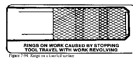
Never stop the carriage while the tool is in contact with the work and the work is still revolving as this will cause wear rings on the work surface (Figure 7-94). Check the operation to ensure that the knurling tool is not forcing the work from the center hole. Keep the work and knurling tool well oiled during the operation. Never allow a brush or rag to come between the rollers and the work or the knurl will be ruined.
Frequently, holes will need to be drilled using the lathe before other internal operations can be completed, such as boring, reaming, and tapping. Although the lathe is not a drilling machine, time and effort are saved by using the lathe for drilling operations instead of changing the work to another machine. Before drilling the end of a workpiece on the lathe, the end to be drilled must be spotted (center-punched) and then center-drilled so that the drill will start properly and be correctly aligned. The headstock and tailstock spindles should be aligned for all drilling, reaming, and spindles should be aligned for drilling, reaming, and tapping operations in order to produce a true hole and avoid damage to the work and the lathe. The purpose for which the hole is to be drilled will determine the proper size drill to use. That is, the drill size must allow sufficient material for tapping, reaming, and boring if such operations are to follow.
The correct drilling speed usually seems too fast due to the fact that the chuck, being so much larger than the drill, influences the operator's judgment. It is therefore advisable to refer to a suitable table to obtain the recommended drilling speeds for various materials, such as Table 4-2 in Appendix A.
Supporting drills in the tailstock
Methods of supporting the twist drill in the tailstock can vary (Figure 7-95). Straight shank drills are usually held in a drill chuck, which is placed in the taper socket of the tailstock spindle. Combination drill and countersinks (center drills), counterbores, reamers, taps, and other small shank cutters can also be supported in this way.

Tapered-shank twist drills may be held directly in the tailstock tapered spindle as long as a good fit exists. If the drill shank is not the correct size, then a drill socket or sleeve may be used in the tailstock spindle.
A twist drill holder is used to support large twist drills with the tailstock center. The drill is inserted into the holder and the tailstock center is placed in the center hole which is located at the rear of the drill holder. The holder will rest on the cross slide or compound rest and must be supported by hand until it is held secure by pressure between the tailstock and headstock. When using this method, never withdraw or loosen the tailstock spindle while the lathe is rotating or the workpiece can be thrown out at the operator. Always stop the machine before attempting to withdraw the twist drill.
Another method of supporting a large twist drill in the tailstock is to fasten a lathe dog to the drill shank and support the rear of the drill with the tailstock center in the center hole in the tang of the drill.
Supporting Drills in the Headstock
The drill can also be held and rotated in the headstock with the work held stationary against the tailstock. Straight shank twist drills are supported in the headstock by a drill chuck or collet which is mounted in the headstock spindle. A universal or independent jaw chuck can also be used to hold and turn twist drills if a headstock drill chuck is not available. Tapered shank twist drills can be mounted in the headstock by using a special adapter, such as a sleeve with an internal taper to hold the tapered drill, while the outside of the sleeve is made to fit into the headstock spindle.
Mounting Work for Drilling
If the work is to be rotated and the twist drill will be fed into the end of the work, the work should be mounted in a chuck, on a faceplate, or in a collet. The center of the hole to be drilled should be accurately marked and punched as described for drilling setups.
Always start holes by using a center drill, since this method will be the most accurate and the most efficient. Center-drill by rotating the spindle at computed drill speed and gently bringing the point of the center drill into the end of the work until the proper depth is reached.
If the twist drill is to be rotated by the headstock spindle and the workpiece is to be supported by a V-center mounted in the tailstock, the work should be carefully positioned by hand and the drill moved lightly into contact with the workpiece before starting the lathe. The workpiece must be well supported during drilling operations to prevent the work from being thrown from the lathe or rotating with the drill.
Drilling Operations
To start the drilling operation, compute the correct RPM for the drill and set the spindle speed accordingly. Ensure the tailstock is clamped down on the lathe ways. The feed is controlled by turning the tailstock handwheel. The graduations on the tailstock spindle are used to determine the depth of cut.
If a large twist drill is used, it should be proceeded by a pilot drill, the diameter of which should be wider than the larger drills web.
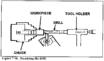
Use a suitable cutting fluid while drilling (Table 4-3 in Appendix A). Always withdraw the drill and brush out the chips before attempting to check the depth of the hole. If the drill is wobbling and wiggling in the hole, use a tool holder turned backwards (Figure 7-96) to steady the drill. Always use a drill that is properly ground for the material to be drilled. Use care when feeding the drill into the work to avoid breaking the drill off in the work. The drill should never be removed from the work while the spindle is turning because the drill could be pulled off the tailstock spindle and cause injury or damage.
Boring is the enlarging and truing of a hole by removing material from internal surfaces with a single-point cutter bit. On the lathe, boring is accomplished in either of these two methods:
Mounting Workpiece for Boring
The workpiece may be supported in a chuck or fastened to a faceplate for boring operations depending upon of the material to be machined. When boring is to be performed on the ends of long stock, the workpiece is mounted in a chuck and a steady rest is used to support the right end near the cutter bit. Some boring operations require the use of special chuck-mounted mandrels to hold workpieces that cannot be successfully mounted otherwise.
Purpose for Boring
Boring is necessary in many cases to produce accurate holes. Drilled holes are seldom straight due to imperfections in the material which cause drills to move out of alignment. Therefore, where accuracy is important, drilled holes are usually made undersize and then bored or reamed to the proper dimensions. Boring is also useful in truing large holes in flat material. In this case, the hole is cut undersize using a bandsaw or trepanning tool and is trued to proper dimensions by boring.
Boring Cutter Bit Setup
The cutter bit used for boring is similar to that used for external turning on the lathe. The bit is usually held in a soft or semisoft bar called a boring tool bar. The boring tool bar (Figure 7-11) is supported by a cutting tool holder which fits into the lathe tool post.
Boring tool bars are supplied in several types and sizes for holding different cutter bits. The bit is supported in the boring tool bar at a 90°, 30°, or 45° angle, depending upon the nature of the workpiece being bored. Most general boring is accomplished with a 90° cutter bit. The bit is mounted at a 30° or 45° angle to the axis of the boring tool bar when it is necessary to cut up to the bottom of a hole or finish the side of an internal shoulder. It is desirable that the boring tool bar be as large as possible without interfering with the walls of the hole. The cutter bit should not extend far beyond the boring tool bar and the bit securely in the bar, yet not have the shank-end protrude far from the bar.
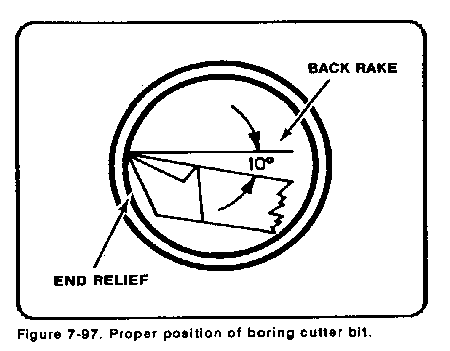
The cutter bits used for boring are shaped like left-hand turning and facing cutter bits. Greater attention must be given to the end clearance angle and the back rake angle because of the curvature of the hole (Figure 7-97).
The boring tool bar should be clamped as close to the holder and tool post as possible considering the depth of boring to be done. The bar will have a tendency to spring away from the workpiece if the bar overhangs the tool post too far. If deep boring is to be performed, it will be necessary that the bar be as thick as possible to counteract this springing tendency.
Straight Boring Operation
The cutter bit is positioned for straight boring operations with its cutting edge set slightly above center. Depending on the rigidity of the setup, the boring tool will have a tendency to spring downward as pressure is applied to the cutting edge. By setting the cutter slightly above center, compensation has been made for the downward spring and the cutter will actually be positioned on the exact center of the workpiece during machining operations (Figure 7-98). The cutting edge faces forward for most operations so the lathe can turn in its normal counterclockwise direction. If it becomes necessary to position the cutter bit against the rear wall of the hole for a special operation, a right-hand turning cutter bit is used and the spindle rotation is reversed.

Position the cutter bit so that the cutting edge is immediately to the right of the workpiece and clears the wall of the hole by about 1/16 inch. Traverse the carriage by hand, without starting the lathe, to move the cutter bit and boring tool bar into the hole to the depth of the intended boring and out again to determine whether there is sufficient clearance to prevent the back of the cutter bit and the boring tool bar from rubbing the inside of the hole. When the clearance is satisfactory, position the cutter bit to the right of the workpiece ready for the first cut. Use the micrometer carriage stop to control the depth of tool travel.
The same speeds recommended for straight turning should be used for straight boring. Feeds for boring should be considerably smaller than feeds used for straight turning because there is less rigidity in the setup. Decrease the depth of cut for each pass of the tool bit for the same reason. It is often advisable to feed the cutter bit into the hole to the desired depth and then reverse the feed and let the cutter bit move out of the hole without changing the depth of feed. It is also good practice to take a free cut every several passes to help eliminate bell mouthing of the workpiece. This practice will correct any irregularities caused by the bit or boring tool bar springing because of the pressure applied to the bit.
The lathe can be used as a device to hold and align a tap or hand die to cut internal or external threads quickly for threads that do not require a high degree of accuracy or a fine finish. More information on taps and dies can be found in TM 9-243.
Hand Tapping on the Lathe
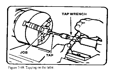
Tapping can be done on the lathe by power or by hand. Regardless of the method, the hole must be drilled with the proper sized tap drill and chamfered at the end. The shank end of the tap is supported by the tailstock center. A slight pressure is maintained against the tap to keep its center hole on the center and to help the cutting teeth of the tap engage the work (Figure 7-99).
The work will rotate when tapping using lathe power. Use a very slow spindle speed (10 to 30 RPM) and plenty of cutting fluid or coolant. Install a tap and reamer wrench on the end of the tap to keep it from turning. Support the wrench on the compound rest. Power is not recommended for taps under 1/2 inch in diameter or when tapping steel. Ensure that the tap wrench handle contacts the compound rest before engaging power or the end of the handle will whip around and could crush a finger or cause other injury or damage. Do not attempt to start the tap into the hole with the work revolving. Always keep the tap snug in the center hole to prevent the tap from coming out of alignment and ruining the threads.
The setup for hand tapping in a lathe is similar to that used in power tapping. The headstock chuck is held steady and not rotated. The tap is turned by using an adjustable wrench. Lock the lathe gears so that the headstock will not move when using a large tap. Back off the tap frequently when tapping to break the chips and allow for a clean thread.
Hand Die Threading on the Lathe
Die threading on a lathe is very similar to tapping on a lathe, except that the die is aligned perpendicular to the work axis by pressure exerted against the back surface of the die. This pressure can be exerted by means of a drill pad, by using the tailstock spindle, or by using the head of the drill chuck for small dies. Die threading can be done using power or by hand, using the same procedures as tapping. Power can be used to remove the die from the work if the die stock handle is swung to the opposite side and low reverse power is used. It is difficult to cut very coarse threads with a die because of the great amount of force needed to turn the die. It is advisable to open up the die to its full width, rough-cut the threads, and then close up the die and go over the threads for a finished size. Always use a lubricant or coolant for this operation.
Reamers are used to finish drilled holes or bores quickly and accurately to a specified diameter. When a hole is to be reamed, it must first be drilled or bored to within 0.004 to 0.012 inch of the finished size since the reamer is not designed to remove much material.
Reaming with a Machine Reamer
The hole to be reamed with a machine reamer must be drilled or bored to within 0.012 inch of the finished size so that the machine reamer will only have to remove the cutter bit marks.
The workpiece is mounted in a chuck at the headstock spindle and the reamer is supported by the tailstock in one of the methods described for holding a twist drill in the tailstock.
The lathe speed for machine reaming should be approximately one-half that used for drilling.
Reaming with a Hand Reamer
The hole to be reamed by hand must be within 0.005 inch of the required finished size.
The workpiece is mounted to the headstock spindle in a chuck and the headstock spindle is locked after the piece is accurately setup The hand reamer is mounted in an adjustable tap and reamer wrench and supported with the tailstock center. As the wrench is revolved by hand, the hand reamer is fed into the hole simultaneously by turning the tailstock handwheel.
The reamer should be withdrawn from the hole carefully, turning it in the same direction as when reaming. Never turn a reamer backward. See Table 4-3 in Appendix A for the proper cutting fluid for reaming. Never use power with a hand reamer or the work could be ruined.
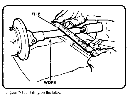
Filing and polishing are performed on the lathe to remove tool marks, reduce the dimension slightly, or improve the finish.
Filing on the Lathe
Mill files are generally considered best for lathe filing. The bastard cut mill type hand file is used for roughing and the second cut mill-type hand file for the finer class of work. Other types such as the round, half-round, and flat hand files may also be used for finishing irregular shaped workpieces. Never use a file without a handle.
For filing ferrous metals, the lathe spindle speed should be four or five times greater than the rough turning speed. For filing nonferrous metals, the lathe spindle speed should be only two or three times greater than the roughing speed. Too slow a speed may cause the workpiece to be filed out of round, while too high a speed will cause the file to slide over the workpiece, dulling the file and glazing the piece.
NOTE: When filing, file left-handed if at all possible to avoid placing your arm over the revolving chuck or lathe dog.
The file is held at an angle of about 10° to the right and moved with a slow sliding motion from left to right so that the teeth will have a shearing action (Figure 7-100). The direction of stroke and angle should never be the opposite, as this will cause chatter marks on the piece. The file should be passed slowly over the workpiece so that the piece will have made several revolutions before the stroke is completed. The pressure exerted on the file with the hands should be less than when filing at the bench. Since there are less teeth in contact with the workpiece, the file must be cleaned frequently to avoid scratching.
Since filing should be used for little more than to remove tool marks from the workpiece, only 0.002 to 0.005 inch should be left for the filing operation.
Polishing on the Lathe
Polishing with either abrasive cloth or abrasive paper is desirable to improve the surface finish after filing. Emery abrasive cloth is best for ferrous metals while abrasive paper often gives better results on nonferrous materials. The most effective speed for polishing with ordinary abrasives is approximately 5,000 feet per minute. Since most lathes are not capable of a speed this great for an average size workpiece, it is necessary to select as high a speed as conditions will permit.
In most cases the abrasive cloth or paper is held directly in the hand and applied to the workpiece, although it may be tacked over a piece of wood and used in the same manner as a file. Improvised clamps may also be used to polish plain round work.
Since polishing will slightly reduce the dimensions of the workpiece, 0.00025 to 0.0005 inch should be allowed for this operation. Figure 7-101 shows how to hold the abrasive strip when polishing. Note that the ends of the strip are separated. This prevents the strip from grabbing and winding around the work, which could pull the operator's hand into the work. Move the polishing strip slowly back and forth to prevent material building up on the strip which causes polishing rings to form on the work. To produce a bright surface, polish the work dry. To produce a dull satin finish, apply oil as the polishing operation is in progress.

Eccentric work is work that is turned off center, or not on the normal center axis. An engine crankshaft is a good example of an eccentric workpiece. Crankshafts normally have a main center axis, called a main journal, and offset axes, which produce the throw and the eccentric diameters of the mechanism. An eccentric shaft may have two or more diameters and several different center axes. The amount of eccentricity, or half of the throw, is the linear distance that a set of center holes has been offset from the normal center axis of the workpiece. Eccentric turning on the lathe is used for the following eccentric turning situations:
When the throw is large enough to allow all centers to be located on the workpiece at the same time.
When the throw is too small to allow all centers to fit into the end of a workpiece at the same time. (The center drilled holes are too large.)
When the throw is so great that all centers cannot be located on the work, or in other words, a throw larger than the largest diameter of the workpiece. (This type of crank is usually made in separate pieces and connected together, since the cost of wasted material would be too great if constructed from one piece on the lathe).
Turning an Eccentric with Center Holes
Before an eccentric workpiece can be machined, it is necessary to center-drill both ends of the workpiece, including the offset centers. If the workpiece is large enough to position all center axes on the work at the same time, the machining operation will be simple and easy.

Additional throws are machined in the same manner. Throw positions may be started by cutting with a parting tool to establish the shoulders, which may aid the turning operation. The tool bit selected will depend on the material to be machined and on the depth of cut desired.
Turning an Eccentric with Close Center Holes
If turning an eccentric that has the different centers placed too close together, a different procedure should be used. Cut the stock 3/4 inch oversized and just face both ends to clean up the saw cuts Lay out and center-drill the normal. center axis and turn down those diameters on the center axis with the work mounted between centers. Remove the work and remount into a chuck. Face both ends to the required length and center-drill the offset centers. Remount the work between these centers and machine the eccentric diameters to size. For eccentric work that has a limited distance between each center, this method is safer than trying to use a very shallow center-drilled hole to hold the work between centers (Figure 7-102).
Turning an Eccentric Using Throw Plates
If the lathe is to be used to turn a crank with a great throw, or a throw that is greater than normally machined on a lathe (Figure 7-102), special throw plates must be fabricated to hold the ends of the work while turning. The special throw plates will be used as support blocks to enable the offset center holes to be machined into the throw plates and allow for eccentric turning. eccentric turning, it is not recommended for normal lathe operations. Special crankshaft turning and grinding equipment is available for this type of machining.
General
Recessing, sometimes called channeling or cambering, is the process of cutting a groove inside of a drilled, bored, or reamed hole. Recesses (Figure 7-103) are usually machined to provide room for the tool runout needed for subsequent operations such as internal threading.
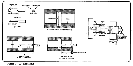
A boring bar and holder may be used as a recessing tool, since recessing tools have the same tool angles and are similar in shape to boring tools. A high-speed steel cutting tool bit, ground with a square nose, makes a satisfactory tool for cutting small chambers (Figure 7-103). The sides of the tool bit taper in from the cutting edge so that the nose of the tool is the widest part. The tool bit must extend from the holder a distance slightly greater than the depth of the chamber to prevent the holder from rubbing the bore of the work.
Machining a Recess
To cut a recess, set up the lathe as in a boring operation. Reference the face of the tool bit to the face of the work; then move the tool bit forward the required distance to the recess by using the micrometer stop or by using the compound rest graduated collar. The compound rest must be set parallel with the ways of the bed for this method. Add the width of the tool bit into the measurement or the recess will not be cut correctly. Position A (Figure 7-103) is the tool aligning to the work, position B is set over to the front shoulder of the recess, and position C is the set over to the back of the recess. Use the cross slide graduated collar to measure the distance to move the tool bit toward the operator, inside of the hole. Spindle speed may have to be reduced due to the shape of the tool bit causing chatter on the work. After cutting the recess, use inside calipers to check the diameter.
General
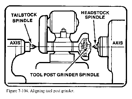
The tool post grinder is a portable grinding machine that can be mounted on the compound rest of a lathe in place of the tool post. It can be used to machine work that is too hard to cut by ordinary means or to machine work that requires a very fine finish. Figure 7-29 shows a typical tool post grinder. The grinder must be set on center, as shown in Figure 7-104. The centering holes located on the spindle shaft are used for this purpose. The grinding wheel takes the place of a lathe cutting tool. It can perform most of the operations that a cutting tool is capable of performing. cylindrical, tapered, and internal surfaces can be ground with the tool post grinder. Very small grinding wheels are mounted on tapered shafts known as quills to grind internal surfaces.
Selection of Grinding Wheels and Speeds
The grinding wheel speed is changed by using various sizes of pulleys on the motor and spindle shafts. An instruction plate on the grinder gives both the diameter of the pulleys required to obtain a given speed and the maximum safe speed for grinding wheels of various diameters. Grinding wheels are safe for operation at a speed just below the highest recommended speed. A higher than recommended speed may cause the wheel to disintegrate. For this reason, wheel guards are furnished with the tool post grinder to protect against injury. Always check the pulley combinations given on the instruction plate of the grinder when you mount a wheel. Be sure that the combination is not reversed, because this may cause the wheel to run at a speed far in excess of that recommended. During all grinding operations, wear goggles to protect your eyes from flying abrasive material.
Dressing the Grinding Wheel
The grinding wheel must be dressed and trued. Use a diamond wheel dresser to dress and true the wheel. The dresser is held in a holder that is clamped to the drive plate. Set the point of the diamond at center height and at a 10° to 15° angle in the direction of the grinding wheel rotation. The 10° to 15° angle prevents the diamond from gouging the wheel. Lock the lathe spindle by placing the spindle speed control lever in the low RPM position.
NOTE: The lathe spindle does not revolve when you are dressing the grinding wheel.
Remove the diamond dresser holder as soon as the dressing operation is completed. Bring the grinding wheel in contact with the diamond by carefully feeding the cross slide by hand. Move the wheel clear of the diamond and make a cut by means of the cross slide. The maximum depth of cut is 0.002 inch. Move the wheel slowly by hand back and forth over the point of the diamond. Move the carriage if the face of the wheel is parallel to the way of the lathe. Move the compound rest if the face of the wheel is at an angle. Make the final depth of cut of 0.0005 inch with a slow, even feed to obtain a good wheel finish.
Before you begin the grinding operation, cover the ways with a heavy piece of paper or use a shallow pan of water placed on the ways to collect the grinding dust that will accumulate from the grinding. This is to ensure none of the grinding burns to the ways or gets under the carriage which will cause the lathe premature wear. If you use a piece of paper, pay close attention that the sparks from the grinding operation do not cause the paper to ignite. If you use a shallow pan of water, make sure water is not spilled on the ways of the lathe. After all grinding operations, thoroughly clean and oil the lathe to remove any grinding dust that the paper pan of water missed.
Grinding Feeds, Speeds, and Depth of Cuts
Rotate the work at a fairly low speed during the grinding operations. The recommended surface foot speed is 60 to 100 FPM. The depth of cut depends upon the hardness of the work, the type of grinding wheel, and the desired finish.
Never take grinding cuts deeper than 0.002 inch Use a fairly low rate of feed. You will soon be able to judge whether the feed should be increased or decreased. Never stop the rotation of the work or the grinding wheel while they are in contact with each other.
Marking Position of Lathe Centers
Tool post grinders are often used to refinish damaged lathe centers. If the lathe is to be used for turning between centers in the near future, grind the tailstock center first, then the headstock center. Leave the headstock center in position for the turning operation. This method provides the greatest degree of accuracy. If you must remove the headstock center in order to perform other operations, marks placed on the headstock center, the sleeve, and the center will enable you to install them in the same position they were in when the center was ground. This will ensure the greatest degree of accuracy for future operations involving turning work between centers.
Setup for Grinding Lathe Centers
To refinish a damaged lathe center, you should first install headstock and tailstock centers after ensuring that the spindle holes, drill sleeves, and centers are clean and free of burrs. Next, position the compound rest parallel to the ways; then, mount the tool post grinder on the compound rest. Make sure that the grinding wheel spindle is at center height and aligned with the lathe centers. Move the compound rest 30° to the right of the lathe spindle axis, as shown in Figure 7-40. Mount the wheel dresser, covering the ways and carriage with rags to protect them from abrasive particles. Wear goggles to protect your eyes.
Grinding Lathe Centers
Start the grinding motor. Turn it on and off alternately, but let it run a bit longer each time, until the abrasive wheel is brought up to top speed. Dress the wheel, feeding the grinder with the compound rest. Then move the grinder clear of the headstock center and remove the wheel dresser. Set the lathe for the desired spindle speed and engage the spindle. Pick up the surface of the center. Take a light depth of cut and feed the grinder back and forth with the compound rest. Do not allow the abrasive wheel to feed entirely off the center. Continue taking additional cuts until the center cleans up. To produce a good finish, reduce the feed rate and the depth of cut to 0.0005. Grind off the center's sharp point, leaving a flat with a diameter about 1/32 inch. Move the grinder clear of the headstock and turn it off.
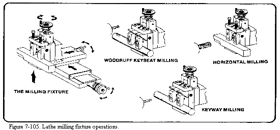
Milling operations may be performed on the lathe by using the Versa-Mil, which is discussed in Chapter 9, and by using the lathe milling fixture. The lathe milling fixture complements the Versa-Mil and adds to the basic capabilities of the machine shop. If the Versa-Mil is out of action or being used for another job, many milling operations can still be accomplished by using the milling fixture (Figure 7-105). Capabilities, functions, and uses are outlined in the appropriate operator's manual, either TM 9-3465-200-10 or TM 9-3465-201-10.
The micrometer carriage stop, shown in Figure 7-28, is used to accurately position the lathe carriage. Move the carriage so that the cutting tool is approximately positioned. Clamp the micrometer carriage stop to the ways of the lathe, with the spindle in contact with the carriage. The spindle of the micrometer carriage stop can be extended or retracted by means of the knurled adjusting collar. The graduations on the collar, which indicate movement in thousandths of an inch, make it possible to set the spindle accurately. Next, bring the carriage in contact with the micrometer spindle again. The carriage can be accurately positioned within 0.001 inch. This is very useful when you are facing work to length, machining shoulders to an exact length, or accurately spacing internal and external grooves. After making a cut, bring the tool back to the start of the cut by means of the carriage stop. This feature is very useful when you must remove a tool, such as the internal recessing tool, from the hole to take measurements and then reposition it to take additional cuts. Always bring the carriage into contact with the stop by hand. Use power feed to bring the carriage within 1/32 inch of the stop. Move the carriage by hand the remaining distance.
General
The steady rest consists of a frame and three adjustable jaws which support the work, as shown in Figure 7-27. One purpose of the steady rest is to prevent springing or deflection of slender, flexible work; another is to furnish auxiliary support for the work to permit heavy cuts to be made; a third is to support work for drilling, boring, or internal threading. The over arm containing the top jaw can be unfastened and swung out of the way so that identical pieces can be removed and replaced without adjusting the jaws.
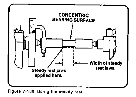
Bearing Surface
A bearing surface must be provided for the steady rest jaws. The bearing surface is usually machined directly on the work, as shown in Figure 7-106. When the work is too small in diameter to machine the bearing surface or shaped so that it would be impractical to machine one, you can use a cathead to provide the bearing surface. The cathead shown in Figure 7-27, has a bearing you surface, a hole through which the work extends, and adjusting screws. The adjusting screws fasten the cathead to the work. They are also used to align the bearing surface so can use a cathead to provide the bearing surface so that t is concentric to the work axis. Use a dial indicator to ensure concentricity.
Setting up the Steady Rest
To setup the rest, first machine and polish the portion of the work that is to be used as the bearing surface. Clean the portion of the ways where the steady rest is to be mounted, place the steady rest on the ways and clamp loosely. Open the top of the steady rest and place the workpiece in the chuck with the bearing surface over the adjustable jaws. Clamp the steady rest securely to the ways. Close the top of the steady rest and adjust the jaws to the workpiece. There should be 0.001 inch clearance between the jaws and the workpiece. Tighten the locking screws on the adjustable jaws. Lubricate the bearing surface generously with a heavy oil before turning the lathe on. Proceed with the machining operation Continuously watch the bearing surface and the adjustable jaws to ensure a film of heavy oil is between them. As the machining operation continues, also check the bearing surface and adjustable jaws as when the workpiece heats up it will expand, closing the distance between the jaws and the workpiece.
Using Steady Rest with Headstock Center
When it is not possible to hold the work in the chuck, you can machine with one end supported by the headstock center and the other end supported by the steady rest. Use a leather strap or rawhide thong to tie the work to the driveplate and to prevent it from moving off the headstock center, as shown in Figure 7-107. Mount the work between centers and machine the bearing surface. Set up the steady rest. With the work mounted between the centers, tie the lathe dog, then remove the tailstock center and perform the necessary machining.

Using the Follower Rest
Long slender shafts that tend to whip and spring while they are being machined require the use of a follower rest (Figure 7-27). The follower rest is fastened to the carriage and moves with the cutting tool. The upper jaw prevents the work from climbing the cutting tool. The lower jaw prevents the work from springing away from the cutting tool The follower rest jaws are adjusted in the same manner as steady rest jaws. The follower rest is often used when long, flexible shafts are threaded, as shown in Figure 7-108. At the completion of each threading cut, remove any burrs that may have formed to prevent them from causing the work to move out of alignment.

Source: http://faculty.ksu.edu.sa/hossainy/Book1/Chapter%207.doc
Web site to visit:http://faculty.ksu.edu.sa
Author of the text: indicated on the source document of the above text
If you are the author of the text above and you not agree to share your knowledge for teaching, research, scholarship (for fair use as indicated in the United States copyrigh low) please send us an e-mail and we will remove your text quickly. Fair use is a limitation and exception to the exclusive right granted by copyright law to the author of a creative work. In United States copyright law, fair use is a doctrine that permits limited use of copyrighted material without acquiring permission from the rights holders. Examples of fair use include commentary, search engines, criticism, news reporting, research, teaching, library archiving and scholarship. It provides for the legal, unlicensed citation or incorporation of copyrighted material in another author's work under a four-factor balancing test. (source: http://en.wikipedia.org/wiki/Fair_use)
The information of medicine and health contained in the site are of a general nature and purpose which is purely informative and for this reason may not replace in any case, the council of a doctor or a qualified entity legally to the profession.
The texts are the property of their respective authors and we thank them for giving us the opportunity to share for free to students, teachers and users of the Web their texts will used only for illustrative educational and scientific purposes only.
All the information in our site are given for nonprofit educational purposes