
Pressure vessels most often contain fluids, vapours or gases at pressure levels greater than that of atmospheric pressure. Pressure vessels contain a wide variety of substances used for various industrial applications including the chemical, pharmaceutical, food and beverage, oil, fuel and plastic industries. The substance contained and the industrial application of the pressure vessels determines such design components as vessel material, size, shape, temperature and pressure level. Vessel creation and maintenance consist of structured steps in which the above factors are determined. When a substance is stored under pressure, the potential for rupture and leakage exists. This risk increases when the substance is toxic or gaseous. Engineers take precautions when creating a pressure vessel to limit the occurrence of vessel failure. The division of vessel creation into steps, which include design, construction, testing and inspection, keeps safety hazards to a minimum.
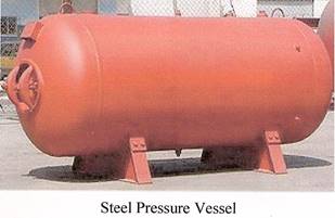
Storage vessels/tanks are simple vessels used for storing liquids, solutions or pharmaceutical raw material and other chemicals. These general purpose vessels made of stainless steel, fibre glass, titanium, galvanised steel etc. and are used by a number of industries to store various substances and solutions. Storage vessels/tanks can either be horizontal or vertical in their orientation. Horizontal storage vessels are generally mounted on stands or saddles and have a access hatch either on the bottom or on the top. Vertical storage vessels are erected vertically and usually have access ports on the bottom. These specialised vessels can either be placed above or below ground, depending on the construction of the storage facility. The wall thickness of the vessel determines the application and the use of the vessel, while single wall storage vessels can be used for general applications, double walls vessels are generally used for high pressure considerations.
The SI derived unit of pressure is the Pascal (PA). Also used is the pound per square inch (PSI).
Improperly operated or maintained pressure vessels can fail catastrophically, kill and injure workers and others and cause extensive damage even if the contents are benign. One of the hazards associated with pressure vessels is operating the vessels above their design limits which can lead to catastrophic weld failure, loss of life and major structural damage to plant and buildings. Another possible hazard is the improper operation of relief devices due to faulty maintenance and failure to test regularly. Other possible hazards include:
Pressure vessels and storage vessels should be inspected regularly to survey the vessel, review any important history or data on the vessel to identify hazards, and prevent vessel rupture or catastrophic failure.
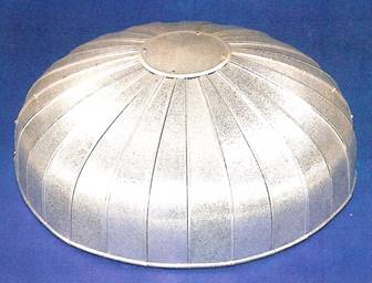
The end caps on a cylindrically shaped pressure vessel are known as heads. The shape of the heads used can vary. The most common head shapes are:
A sphere is an ideal shape for a head, because the pressure in the vessel is divided equally across the surface of the head. The radius (R) of the head equals the radius of the cylindrical part of the vessel.
This is also called a 2:1 elliptical head. The shape of this head is more economical, because the height of the head is just a quarter of the diameter. Its radius varies between the major and minor axis.
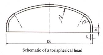
These heads have a dish with a fixed radius (r1), the size of which depends on the type of torispjerical head. The transition between the cylinder and the dish is called the knuckle. The knuckle has a toroidal shape. The most common types of torispherical head is the klopper head. This is a thorispherical head. The dish has a radius that equals the diameter of the cylinder it is attached to (f1 = Do). The knuckle has a radius that equals a tenth of the diameter of the cylinder (r2 = 0.1 D0).
The tank or vessel is carefully measured to avoid costly errors and mistakes leading to waste of time and materials, financial penalties and or loss of productivity to the contractor.
It is very important to study the tanks or vessels when measuring so as to study their location; where they are situated and their proximity to other obstacles such as walls, ceilings, pipe work and other equipment which may be nearby.
When measuring a tank or vessel, a number of things should be taken into consideration:
It is always a good idea to make a detailed sketch or scaled drawing of the vessel and its features as this will save time when manufacturing and installing the cladding for the vessel. Detailed drawings force you, to a certain extent, to consider different aspects of the job which might otherwise go unnoticed such as;
Refer to Module 2 – Unit 2 – Orthographic Projections.
Diameter = Radius x 2 or D = 2r.
Π = 3.14
Circumference ÷ π = Diameter Radius = Diameter ÷ 2.
Example: The circumference of a vessel = 9420mm – Find the diameter and the radius of the vessel.
Diameter = Circumference ÷ π = 9420 ÷ 3.14 = 3000mm
Radius = Diameter ÷ 2 = 3000mm ÷ 2 = 1500mm
The tangent line refers to the point of contact (tangency) between the cylinder and the knuckle portion of the vessel head. The distance from the tangent line on one head to the tangent line on the opposite head is known as tangent to tangent or T/T.
Example: A vessel is 1.5 metres in diameter and 4 metres long. Find the total surface area of the vessel and the volume of the vessel.
Surface Area
Π = 3.14 r = radius d = diameter l = length
Area of a circle =πr².
Area of one end of tank = 3.14 x 0.75² = 1.77mt²
Area of 2 ends = 1.77mt² x 2 = 3.54mt²
Area of cylindrical section of tank = π x d x l = 3.14 x 1.5 x 4 = 18.84mt².
Total surface area of tank = 3.54 mt² + 18.84 mt² = 22.38mt².
Volume
Volume of tank = πr²l = 3.14 x 0.75² x 4 = 7.06mt³
An array of differing national regulations, standards, and codes for pressure vessels has been replaced by a single European directive. The European Union has adopted more than 40 European standards for boilers, pipes and flanges, as well as supporting standards for materials, welding and testing. The latest addition to the approved standards is DIN EN 13445, which covers the design and fabrication of unfired pressure vessels and their parts. The standards cover such areas as:
Refer to module 2 – Geometry and pattern development.
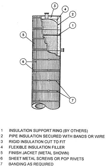
After the patterns/sheets have been marked out, they are ready for cutting on the guillotine or power hand shears. Use a hand snips for any notching of the pattern. Once the patterns have been cut out they are now ready to be punched using a hand punch or a multi-linear punching machine. The patterns are then folded, rolled and swaged to suit the piece required. The figure below shows the assembly details of insulation and profiled cladding to a small vessel.
All joints in the cladding should be suitably overlapped and arranged to shed water and if the vessel is located outdoors, all joints should be sealed with waterproof mastic.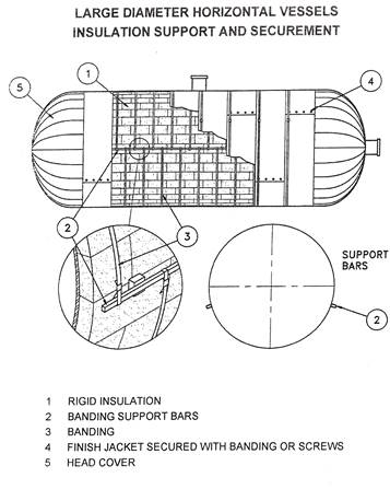
The insulation vessel can be a small or large rectangular or cylindrical tank or vessel, erected in a vertical or horizontal position. The specified insulation of suitable thickness and density is selected and cut to size. It is firmly secured to the vessel with metal bands, adhesive or a combination of both. Alternatively the insulation may be impaired over pins fixed to the surface of the vessel at recommended centres. Location of the pins should be arranged so that there is a pin no more than 50mm from each corner of the insulation. Another method of supporting the insulation on vertical surfaces on larger circular tanks or vessels is to fit circumferential support rings, spaced at distances which will provide adequate support according to the weight of the insulation. The support rings shall protrude from the vessel slightly less than the thickness of the insulation.
All joints should be closely butted together. Vertical joints (and in multi-layer applications all joints) must be staggered. The corners on rectangular tanks should be overlapped by adjacent slabs to the thickness of the insulation. When using pins with spring clip washers, the length of the pin should be 10mm less than the thickness of the insulation to avoid hot spots on the cladding.
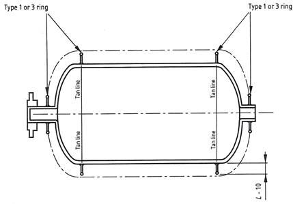
As part of the support system for both the insulation and the cladding on vertical piping, or vertical/downward facing vessels and equipment, attachments such as angle iron and flat bar can be welded to the vessel (usually carried out by the manufacturers’ of the vessel or equipment). These attachments provide a secure base for secondary angle rings and other secondary supports. The spacing is determined by the maximum permitted span under wind loading conditions for the cladding used.
L = thickness of insulation.

L = thickness of insulation.
Typical insulation supports for vessels.
There are a number of different sources of information which can be used for general information and specifications such as;
Pressure vessels contain a wide variety of substances used for various industrial applications including the chemical, pharmaceutical, food and beverage, oil, fuel and plastic industries. When a substance is stored under pressure, the potential for rupture and leakage exists. This risk increases when the substance is toxic or gaseous. Engineers take precautions when creating a pressure vessel to limit the occurrence of vessel failure.
Storage vessels/tanks are simple vessels used for storing liquids, solutions or pharmaceutical raw material and other chemicals. These general purpose vessels made of stainless steel, fibre glass, titanium, galvanised steel etc. and are used by a number of industries to store various substances and solutions.
The end caps on a cylindrically shaped pressure vessel are known as heads. The shape of the heads used can vary. The most common head shapes are: Hemispherical head, Ellipsoidal head and a Torispherical head.
An array of differing national regulations, standards, and codes for pressure vessels has been replaced by a single European directive. The latest addition to the approved standards is DIN EN 13445, which covers the design and fabrication of unfired pressure vessels and their parts.
Source: http://local.ecollege.ie/Content/APPRENTICE/liu/ind_insulation/mod5/m5_u7.doc
Web site to visit: http://local.ecollege.ie
Author of the text: indicated on the source document of the above text
If you are the author of the text above and you not agree to share your knowledge for teaching, research, scholarship (for fair use as indicated in the United States copyrigh low) please send us an e-mail and we will remove your text quickly. Fair use is a limitation and exception to the exclusive right granted by copyright law to the author of a creative work. In United States copyright law, fair use is a doctrine that permits limited use of copyrighted material without acquiring permission from the rights holders. Examples of fair use include commentary, search engines, criticism, news reporting, research, teaching, library archiving and scholarship. It provides for the legal, unlicensed citation or incorporation of copyrighted material in another author's work under a four-factor balancing test. (source: http://en.wikipedia.org/wiki/Fair_use)
The information of medicine and health contained in the site are of a general nature and purpose which is purely informative and for this reason may not replace in any case, the council of a doctor or a qualified entity legally to the profession.
The texts are the property of their respective authors and we thank them for giving us the opportunity to share for free to students, teachers and users of the Web their texts will used only for illustrative educational and scientific purposes only.
All the information in our site are given for nonprofit educational purposes