
SECTION 13 FATIGUE
13.1 General - This section applies to the design of structures and structural elements subject to loading which could lead to fatigue failure. The following effects are not considered in the section.
a) Corrosion fatigue
b) Low cycle (high stress) fatigue
c) Thermal fatigue
d) Stress corrosion cracking
e) Effects of high temperature (> 150o C)
f) Effects of low temperature (< brittle transition temperature)
13.1.1 Basis - For the purpose of design against fatigue, different details (of members and connections) are classified under different fatigue class. The design stress range corresponding to various number of cycles, are given for each fatigue class. The requirements of this section shall be satisfied with, at each critical location of the structure subjected to cyclic loading, considering relevant number of cycles and magnitudes of stress range expected to be experienced during the life of the structure.
13.2Definitions
Constant Stress Range - The amplitude between which the stress ranges under cyclic loading is constant during the life of the structure or a structural element.
Cumulative Fatigue - Total damage due to fatigue loading of varying stress range.
Cut-off Limit - The stress range, corresponding to the particular detail, below which cyclic loading need not be considered in cumulative fatigue damage evaluation (corresponds to 108 numbers of cycles in most cases).
Design Life -Time Period for which a structure or a structural element is required to perform its function without fatigue damage.
Design Spectrum - Frequency distribution of the stress range from all the nominal loading events during the design life.
Detail Category - Designation given to a particular detail to indicate the S-N curve to be used in fatigue assessment.
Fatigue - Damage caused by repeated fluctuations of stress, leading to progressive and consequent cracking of a structural element.
Fatigue Strength - Stress range for a category of detail, depending upon the number of cycles it is required to withstand.
S-N curve – Curve, defining the relationship between the number of stress cycles to failure (Nsc)at a constant stress range (Sc), during fatigue loading parts of a structure.
Stress Cycle Counting - Sum of individual stress cycles from stress history arrived at using any rational method.
Stress Range - Algebraic difference between two extremes of stresses in a cycle of loading.
Stress Spectrum - Histogram of stress cycles produced by a nominal loading event.
13.3 Design
13.3.1 Reference Design Condition - The standard S-Ncurves for each detail category are given for the following conditions:
The values obtained from the standard S-N curve shall be modified by a capacity reduction factor mr, when any of the above conditions do not apply. The capacity reduction factor, mr to account for the detail in a non-redundant load path shall be taken as 0.70. To account for thickness of plates greater than 25 mm and joined together by transverse fillet welding, the capacity reduction factor shall be modified by the factor
mr = (25/tp)0.25 £ 1.0
where
tp = actual thickness in mm of the thicker plate being joined
The two factors are applied cumulatively when the both the conditions are encountered. Fatigue need not be investigated if condition in 13.3.2.3, 13.6.1, or 13.7 is satisfied.
13.3.2 Design Spectrum
13.3.2.1 Stress Evaluation- The design stress shall be determined by elastic analysis of the structure to obtain stress resultants and the local stresses may be obtained by a conventional stress analysis method. The normal and shear stresses shall be determined considering all design actions on the members, but excluding stress concentration due to the geometry of the detail. The stress concentration, however, not characteristic of the detail shall be accounted for in the stress calculation.
In the fatigue design of trusses made of members with open sections in which the end connections are not pinned, the stresses due to secondary bending moments shall be taken into account, unless the slenderness ratio, (KL/r), of the member is less than 40.
In the determination of stress range at the end connections between hollow sections, the effect of connection stiffness and eccentricities may be disregarded, provided
a) The calculated stress range is multiplied by appropriate factor given in Table 13.1(a) in the case of circular hollow section connections and Table 13.1(b) in the case of rectangular hollow section connections.
b) The design throat thickness of fillet welds in the joints is greater than the wall thickness of the connected member.
TABLE 13.1(a) MULTIPLYING FACTORS FOR CALCULATED STRESS RANGE
(Circular Hollow Sections)
(Section 13.3.2.1)
Types of connection |
Chords |
Verticals |
Diagonals |
|
Gap connections |
K type |
1.5 |
1.0 |
1.3 |
N type |
1.5 |
1.8 |
1.4 |
|
Overlap connections |
K type |
1.5 |
1.0 |
1.2 |
N type |
1.5 |
1.65 |
1.25 |
|
TABLE 13.1(b) MULTIPLYING FACTORS FOR CALCULATED STRESS RANGE
(Rectangular Hollow Sections)
(Section 13.3.2.1)
Types of Joint |
Chords |
Verticals |
Diagonals |
|
Gap connections |
K type |
1.5 |
1.0 |
1.5 |
N type |
1.5 |
2.2 |
1.6 |
|
Overlap connections |
K type |
1.5 |
1.0 |
1.3 |
N type |
1.5 |
2.0 |
1.4 |
|
13.3.2.2 Design Stress Spectrum - In the case of loading events producing non-uniform stress range cycle, the stress spectrum may be obtained by a rational method, such as “Rain flow counting” or an equivalent method.
13.3.2.3 Low Fatigue - Fatigue assessment is not required for a member, connection or detail, if normal and shear design stress ranges, f, satisfy the following conditions:
![]()
or if the actual number of stress cycles, NSC, satisfies
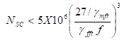
where
gmft , gfft = partial safety factors for strength and load, respectively (13.3.3)
f = actual fatigue stress range for the detail
13.3.3 Partial Safety Factors
13.3.3.1 Partial Safety Factor for Actions and their effects (gfft) - Unless and otherwise the uncertainty in the estimation of the applied actions and their effects demand a higher value, the partial safety factor for loads in the evaluation of stress range in fatigue design shall be taken as 1.0.
13.3.3.2 Partial Safety Factor for Fatigue Strength (gmft) - The partial safety factor for strength is influenced by consequences of fatigue damage and level of inspection capabilities.
Based on consequences of fatigue failure, component details have been classified as given in the Table 13.2.
TABLE 13.2 PARTIAL SAFETY FACTORS FOR FATIGUE STRENGTH (gmft)
Inspection and Access |
Consequence of failure |
|
Fail-safe |
Non-fail-safe |
|
Periodic inspection and maintenance, accessibility to detail is good |
1.00 |
1.25 |
Periodic inspection and maintenance, poor accessibility for detail |
1.15 |
1.35 |
13.4 Detail Category
Table 13.3 indicates the classification of different details into various categories for the purposes of assessing fatigue strength.
13.5 Fatigue Strength
The fatigue strength of the standard detail for the normal or shear fatigue stress range, not corrected for effects discussed in 13.3.1, is given below (Fig 13.1,13.2):
when ![]()
![]()
when ![]()
![]()
Shear stress
![]()
where
ff, tf = design normal and shear fatigue stress range of the detail, respectively, for life cycle of NSC
ffn,tfn = normal and shear fatigue strength of the detail for 5 x10⁶ cycles
Detail Category |
Constructional Details |
|
Illustration (See Note) |
Description |
|
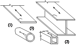
118 |
|
ROLLED AND EXTRUDED PRODUCTS
Sharp edges, surface and rolling flaws to be removed by grinding in the direction of applied stress. |
103 |
|
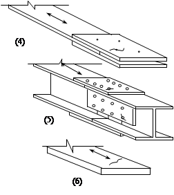
BOLTED CONNECTIONS(4) & (5) Stress range calculated on the gross section and on the net section. |
92 |
|
MATERIAL WITH MACHINE GAS-CUT EDGES WITH DRAGLINES OR MANUAL GAS-CUT MATERIAL (7) |
Note: The arrow indicates the location and direction of the stresses acting in the basic material for which the stress range is to be calculated on a plane normal to the arrow
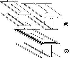
TABLE 13.3 (2) DETAIL CATEGORY CLASSIFICATION GROUP 2 WELDED DETAILS-NOT IN HOLLOW SECTIONS
(Section 13.4)
Detail Category |
Constructional Details |
|
Illustration (See Note) |
Description |
|
92 |
|
WELDED PLATE I-SECTION AND BOX GIRDERS WITH CONTINUOUS LONGITUDINAL WELDS |
83 |
|
WELDED PALTE I-SECTION AND BOX GIRDERS WITH CONTINUOUS LONGITUDINAL WELDS |
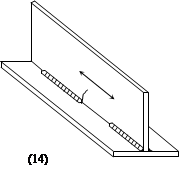
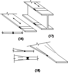
(13) 66 |
|
WELDED PLATE I-SECTION AND BOX GIRDERS WITH CONTINUOUS LONGITUDINAL WELDS |
Note: The arrow indicates the location and direction of the stresses acting in the basic material for which the stress range is to be calculated on a plane normal to the arrow
(continued)
TABLE 13.3 (2) (continued)
Detail Category |
Constructional Details |
|
Illustration (See Note) |
Description |
|
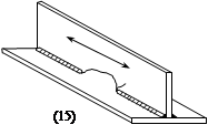
59 |
|
INTERMITTENT LONGITUDINAL WELDS |
52 |
|
INTERMITTENT LONGITUDINAL WELDS |
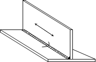
83 |
|
TRANSVERSE BUTT WELDS (COMPLETE PENETRATION) |
Note: The arrow indicates the location and direction of the stresses acting in the basic material for which the stress range is to be calculated on a plane normal to the arrow (continued)
TABLE 13.3 (2) (continued)
 Detail Category Detail Category |
Constructional Details |
|
Illustration (See Note) |
Description |
|
66
|
|
TRANSVERSE BUTT WELDS (COMPLETE PENETRATION) |
59
|
|
TRANSVERSE BUTT WELDS (COMPLETE PENETRATION) |
|
|
TRANSVERSE BUTT WELDS (COMPLETE PENETRATION) |
TABLE 13.3 (2) (continued)
Detail Category |
Constructional Details |
||
Illustration (See Note) |
Description |
||
37 |
|
TRANSVERSE BUTT WELDS (COMPLETE PENETRATION) |
|
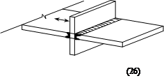
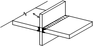
52 |
|
CRUCIFORM JOINTS WITH LOAD-CARRYING WELDS |
|
41 |
(27) |
|
(27) Partial penetration or fillet welds with stress range calculated on plate area. |
27 |
(28) |
(28) Partial penetration or fillet welds with stress range calculated on throat area of weld. |
|
|
Stresses area
Taper < 1:2 |
OVERLAPPED WELDED JOINTS |
|
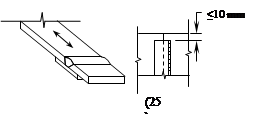
Note: The arrow indicates the location and direction of the stresses acting in the basic material for which the stress range is to be calculated on a plane normal to the arrow
(continued)
TABLE 13.3 (2) (continued)
Detail Category |
Constructional Details |
|||
Illustration (See Note) |
Description |
|||
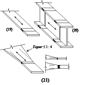
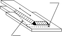
|
(30) |
|
(30) Fillet welded lap joint, with welds and main plate both having a design capacity greater than the overlapping elements. |
|
33 |
(31) |
(31) Fillet welded lap joint, with main plate and overlapping elements both having a design capacity greater than the weld. |
||
|
(32) |
(33) |
|
WELDED ATTACHEMENTS (NON-LOAD CARYING WELDS) LONGITUDINAL WELDS (33) Gusset welded to the edge of a plate or beam flange. Smooth transition radius (r), formed by machining or flame cutting plus grinding. Class of detail varies according to r/b ratio as noted. |
¾ |
1/3£ r/b |
|||
59 |
l£ 50mm |
¾ |
||
52 |
50< l £100mm |
1/6£r/b<1/3 |
||
37 |
100mm<l |
¾ |
||
33 |
¾ |
r/b<1/6 |
||
|
|
WELDED ATTACHMENTS(34) Shear connectors on base material (failure in base material). |
||
Note: The arrow indicates the location and direction of the stresses acting in the basic material for which the stress range is to be calculated on a plane normal to the arrow
(continued)
TABLE 13.3 (2) (continued)
Detail Category |
Constructional Details |
||
Illustration (See Note) |
Description |
||
t (36) |
t £ 12mm
|
|
TRANSVERSE WELDS(35) Transverse fillet welds with the end of the weld ³10 mm from the edge of the plate.
|
52 |
t > 12mm |
||
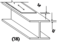
|
tf or tp £25 mm |
|
COVER PLATES IN BEAMS AND PLATE GIRDERS |
27 |
tf or tp > 25 mm |
||
|
|
WELDS LOADED IN SHEAR(39) Fillet welds transmitting shear. Stress range to be calculated on weld throat area. |
|
TABLE 13.3 (3) DETAIL CATEGORY CLASSIFICATION GROUP 3 BOLTS
(Section 13.4)
Detail Category |
Constructional Details |
|
Illustration (See Note) |
Description |
|
|
(41) |
(41) BOLTS IN SHEAR (8.8/TB BOLTING CATEGORY ONLY)Shear stress range calculated on the minor diameter area of the bolt (Ac). |
|
(42) |
(42) BOLTS AND THREADED RODS IN TENSION (tensile stress to be calculated on the tensile stress area At) Additional forces due to prying effects shall be taken into account. For tensional bolts, the stress range depends on the connection geometry. |
Note: The arrow indicates the location and direction of the stresses acting in the basic material for which the stress range
is to be calculated on a plane normal to the arrow.
Source: http://www.buildnova.com/buildnovav3/IS800/IS800SECTION13.doc
Web site to visit: http://www.buildnova.com
Author of the text: indicated on the source document of the above text
If you are the author of the text above and you not agree to share your knowledge for teaching, research, scholarship (for fair use as indicated in the United States copyrigh low) please send us an e-mail and we will remove your text quickly. Fair use is a limitation and exception to the exclusive right granted by copyright law to the author of a creative work. In United States copyright law, fair use is a doctrine that permits limited use of copyrighted material without acquiring permission from the rights holders. Examples of fair use include commentary, search engines, criticism, news reporting, research, teaching, library archiving and scholarship. It provides for the legal, unlicensed citation or incorporation of copyrighted material in another author's work under a four-factor balancing test. (source: http://en.wikipedia.org/wiki/Fair_use)
The information of medicine and health contained in the site are of a general nature and purpose which is purely informative and for this reason may not replace in any case, the council of a doctor or a qualified entity legally to the profession.
The texts are the property of their respective authors and we thank them for giving us the opportunity to share for free to students, teachers and users of the Web their texts will used only for illustrative educational and scientific purposes only.
All the information in our site are given for nonprofit educational purposes


 46
46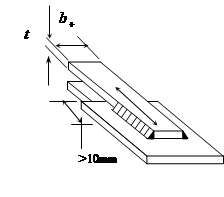 41
41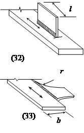 66
66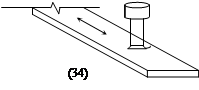 59
59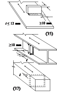
 37
37
 59
59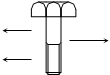 74
74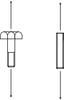 27
27