
Introduction
Specific materials and drawing instruments are required in order to undertake technical drawing. As technical drawing is now a universal language it is governed by rules regarding methods of drawing and the symbols used. Those rules and symbols are laid down in ISO (International Standards Organisation) standards. British Standards (BS) follows the ISO standards.
BS:308 Engineering drawing practice and BS:1192 are both based on ISO:128 Technical drawings - general principles. Figure 1 shows some examples of symbols from BS:308 Engineering drawing practice. The same symbols would be found in ISO:128 Technical drawings - general principles.

Figure 1 - BS:308 Technical Drawing
The ISO also specifies an ‘A’ size series of drawing sheets for technical drawings. Figure 2 shows the basic A0 sheet, the area of which is 1 square metre.

Figure 2 - Sizes of an A0 Size Drawing Sheet
Other A size sheets are A1, A2, A3, A4 and A5. All A size sheets have their edge lengths in the same proportion. This proportion is in the ratio of short side: long side = 1:Ö2.
Each lower size sheet in the A series is obtained by exactly dividing the A sheet along its middle as shown in Figure 3. This results in the following range of sizes.
A0 = 841 mm X 1189 mm = 1 square metre
A1 = 841 mm X 594 mm
A2 = 594 mm X 420 mm
A3 = 420 mm X 297 mm
A4 = 297mm X 210mm
A5 = 210 mm X 148 mm

Figure 3 - Some of the A Size Series of Drawing Sheet
There are larger size A sheets (e.g. 2A0, 4A0) and smaller (e.g. A6) than these. In school, college and examination technical drawing the sizes most commonly used are A2, A3 and A4 sheets.
Papers are commonly measured by their weight - known as so many grams per square metre - gsm. Technical drawing papers are measured in this way. Papers suitable for technical drawings are:
The following minimum set of instruments is required in order to construct good quality technical drawings:

Figure 5 - Adjustable Set Square - Can be set to any Angle between 45 Degrees and 90 Degrees

Figure 6 - 150mm Compass and a Spring Bow Compass

Figure 7 - Positioning the Lead of a Pencil Compass
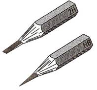
Figure 8 - Sharpening of 2H (or 3H) and HB Pencil Points
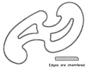
Figure 9 - 'French Curve'
There are many different shapes of these curves. They are chamfered along their upper edges to allow them to be used when drawing with ink pens.

Figure 10 - Metric Radius Curve
A minimum set of equipment for the production of good quality drawings would be:
Figure 11 shows two typical drawing sheet layouts for school or college use when working on A2, A3 or A4 sheets of drawing paper. The sheets can be in either an upright position, which is known as 'portrait' or in a horizontal position, known as 'landscape'. Note the following:

Figure 11 - Drawing Sheet Layouts Suitable for School or College Technical Drawings
Figure 12 shows a type of sheet layout, which may be found in use by engineering companies. The sheets will be pre-printed so that draughtsmen can start working on the sheet without having to add details such as those shown in the title block. Note also the set of reference numbers around the margins of this sheet - anyone using the drawing can indicate any part by reference to the marginal letters and figures.

Figure 12 - Example of a Drawing Sheet Layout such as would be used in an Engineering Company
Figure 13 shows the type of lettering, which should be used in technical drawings. Lettering should be simple, so that it can be easily read. As mentioned above, the height of letters should vary according to the size of drawing sheet in use. Notes and dimension lettering and figures should be drawn at a lower height than title block lettering. For example, on A4 sheets 3 mm high notes and dimension figures would be suitable; on an A2 sheet a height of 5 or 6 mm would be better.
Figure 14 shows some of the types of lines for technical drawings. Note that the lines for the outline of drawings should be thicker than other lines. This makes the outline stand out clearly against the other details in your drawings. BS:308 recommends that outlines should be about twice as thick as other lines.

Figure 14 - Types of Line for Technical Drawings
When a session of drawing is finished, it is important that the equipment, which has been in use,is stored neatly in clean and dry conditions. Dirty and damaged equipment does not help in the production of good, neat and clean drawings. Drawing boards can be either placed in purpose-made racks or stacked one on top of the other. Tee squares should be placed in properly made racks, which make sure that the drawing edges are not damaged and that their two parts do not become separate. Set squares must be kept in a clean condition. They may pick up dust and erasing particles and if they are stored in such a condition other equipment becomes dirty. Pencils can be placed in racks made from blocks of wood with appropriately sized holes. Compasses are easily damaged if not stored properly.
The best method of storing drawings is for each pupil or student to have a folder in which his or her drawings can be placed without their being folded. Other drawings, such as those used to demonstrate the principles of working should be stored flat in drawers large enough to take them unfolded. Take care when placing drawings in folders or drawers. Careless handling can easily cause them to become damaged, even to be torn. Drawings must be kept clean if they are to be read easily.
Figure 15 shows a box, made from wood and hardboard and designed to hold a set of technical drawing equipment. The main dimensions of the box are:
Dimensions in technical drawings are very important. Most drawings will require dimensioning, although some drawings of assemblies may not. Without precise and correct dimensioning most drawings are often of little value. Figure 16 shows the ISO:128 methods of dimensioning lengths, circles and arcs. Note the following:

Figure 16 - Methods of Dimensioning Technical Drawing
Technical drawing is the major design method by which ideas about the shape, form, dimensions, materials, machining methods and finishes of articles being made or constructed are passed between those working in the manufacturing and building industries. These industries are increasingly using computers for the production of their technical drawings. It is possible at the present time for a skilled computer operator to be able to design and draw very advanced drawings on a PC (Personal Computer) with the aid of those computer software packages known as CAD (Computer Aided Design). There are many CAD software packages available at the present day for use on a computer, which will stand on the desk of a draughtsman. For the purpose of describing CAD, we will only be dealing with two of these packages. The first AutoCAD- is expensive but is capable of producing any technical drawing, no matter how complicated in the hands of a skilled operator. AutoCAD is by far the most popular of all. There are more CAD workstations equipped with AutoCAD throughout the world than any other package. The second - AutoSketch- is an inexpensive CAD package for constructing 2-D (two-dimensional) drawings. Both packages are produced and sold by the same firm Autodesk.
When working with the aid of CAD, in place of a drawing board, Tee square, other instruments and pencils, drawings are constructed on a computer monitor screen with the aid of the computer keyboard and a hand controlled 'pointing device'. The computer, its monitor, keyboard and pointing device are known as a workstation. See Figure 17.
A typical workstation comprises:

Figure 17 - PC (Personal Computer) with a Variety of 'Pointing Devices' set up as a CAD Workstation

Figure 18 - Computer Monitor Screen Showing a Drawing Constructed in AutoCAD
Only one of these pointing devices is usually fitted to the computer, although some operators prefer to have two fitted so as to be able to use either at anyone time. The monitor screen in Figure 17 shows a drawing in an AutoCAD drawing editor on the monitor screen and Figure 18 shows more clearly details of the drawing in the drawing editor on the screen.
Figure 19 is what is known as a screen dump of the monitor screen shown in Figure 18. It shows what the drawing editor with its drawing actually looks like. Note the following:
There are many reasons why CAD is now being increasingly used in industry:
Even the most skilled computer expert working as a draughtsman with a CAD system must have a good technical drawing background. Without a good knowledge of the practice of technical drawing methods learned 'at the drawing board', a CAD operator cannot produce technical drawings with his/her equipment. It is only by practising with the aid of drawing instruments that computer drawing skills can be gained. A good practical knowledge of plane and solid geometry, an understanding of the theory of orthographic projection, the use of good standard drawing conventions can only be learned by constant practice 'at the drawing board'. So - first learn how to produce good quality technical drawings 'by hand', then learn how to produce them with CAD.
One major feature of all CAD software packages is the use of the command ZOOM. A computer monitor screen is smaller than the sheet of paper, which a draughtsman would be using. Because of this when a drawing of say A2 size is on screen, some small parts of the drawing may not be easily drawn. With the aid of ZOOM, even the smallest area of the drawing can be examined and drawn on. Figure 20 shows details from the drawing in Figure 19 after part of the drawing has been placed in a ZOOM window. Note the command and prompt names in the menu on the right of the screen. The prompt Window is highlighted in the zoom menu. A window in CAD terms is a small area from part of the screen.
Another feature common to CAD packages is two-dimensional (2-D) coordinates. These allow any point on a screen to be determined in terms of x and y. Units horizontally are in x units, units vertically are in y units. Anyone point on screen is then determined in terms of x,y. If one is working on a screen configured to allow a drawing to be constructed as if on an A3 sheet of drawing paper, the screen would be set so that the drawing editor on screen is 420 units wide and 297 units high (A3 paper is 420 mm by 297 mm). In this case any point on the screen can be determined in units taken from the bottom left hand corner of the screen. Thus the bottom left hand corner is x,y = 0,0; the top right hand corner is x,y = 420,297. Figure 21 shows the x,y positions of four points on a computer screen.
Figure 22 shows a simple line outline within which a circle and a square have been drawn. In a CAD system, a typical method of working to construct this outline could be by typing commands and coordinate numbers at the keyboard. In AutoCAD as the details are typed, they would appear at the command line at the bottom of the drawing editor. In AutoCAD such a sequence would be:
Command: line
From point: 100,200
To point: 250,200
To point: 250,150
To point: 350,150
To point: 350,80
To point: 170,80
To point: 170,150
To point: 100,150
To point: close
Command:
Outline drawn
Command: circle
Circle centre: 130,175
Radius: 25
Circle drawn
Command: line
From point: 300,130
To point: 330,130
To point: 330,100
To point: 300,100
To point: close
Command:
Square drawn
At first glance this sequence may appear to take more time than if the drawing was constructed by hand at a drawing board, but the pointing devices have buttons, which allow rapid changes between the different commands. Also many of the commands are keyed in with a single letter abbreviation - thus LINE is keyed in as 1, CIRCLE is entered as c. The commands can be picked from the menus on the screen - an arrow, moved by movement of the pointing device is placed over a menu name and a pointing device button pressed, which causes the command name to appear in the command line. It is the combined use of a pointing device - mouse, puck, etc. - and entering letters and figures at the keyboard that allows a skilled operator to work very speedily in producing drawings on screen.
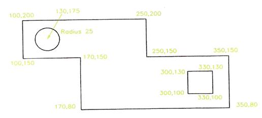
Figure 22 - Drawing Constructed in CAD by Typing Coordinate Positions of Points
It is 3-D (three-dimensional) drawing that CAD excels at in industrial work. In very advanced CAD systems such as AutoCAD (among others), drawings can be produced in 3-D. The 2-D coordinate system is replaced with a 3-D coordinate system with an extra z coordinate - its positive direction is as if it were coming out of the screen towards the operator. It is not so much the value of the actual 3-D drawing that is so important, it is that such 3-D drawings can be shaded and coloured (rendered) to appear as if they were photographs of the component the drawing is portraying. In addition, in engineering industries, the mathematical data for a 3-D drawing held in the computer file for the drawing, can be passed on computer aided machinery and the component actually made in such machines from the data in the file. This method of production is known as Computer Aided Machining (CAM). It must be noted that it is only advanced CAD packages, which can be used for passing data to CAM machinery in this manner.
Note how important the learning of technical drawing skills is. When one has acquired good basic technical drawing skills at the drawing board, this leads onto CAD and CAM in modern engineering industry. In building and architecture similar systems are used. In building the CAD systems are known as Architectural Engineering Computing (AEC) packages.
AutoSketch is a typical 2-D CAD system. Many such packages are available at present and all are relatively inexpensive. They only allow 2-D drawings to be constructed and most work in a similar manner to that already described for drawing in AutoCAD - by selecting or typing commands, followed by selecting points on screen with a pointing device or typing coordinates from the keyboard.
One of the more interesting features in CAD software in recent years has been their development for use in the major software system known as Windows.
Figure 23 is an example of a drawing constructed in the AutoCAD for Windows package.
There are many advantages of drawing with CAD packages developed for working in Windows. Among these are that an operator can work in several computer packages during one session of work. For example:

Figure 23 - Drawing Constructed in AutoCAD for Windows
Questions on Background Notes – Module 6.Unit 2
1. List three main reasons why C.A.D is now vastly used in Industry.
2. When using C.A.D, your workstation consists of a monitor, keyboard and a hand
controlled ‘pointing device’ which controls the curser on the screen, name two of
these devices.
1.
Computer Aided Drawing: C.A.D
of the time it takes for a draughtsman to produce the same drawing.
ease, which saves having to draw the same detail twice.
great accuracy. Drawings can be saved to computer disc, the space
|
2.
Mouse: Graphics Tablet with a Puck: Trackerball: Joystick:
|
3.
The 2-D coordinate system is replaced with 3-D coordinate system 3-D drawings can be shaded and coloured (rendered) to appear as if In engineering industries, the mathematical data for a 3-D drawing
|
Source: http://local.ecollege.ie/Content/APPRENTICE/liu/metalfab_notes/module6/Drawing%20Equipment_M6_U2.doc
Web site to visit: http://local.ecollege.ie/
Author of the text: indicated on the source document of the above text
If you are the author of the text above and you not agree to share your knowledge for teaching, research, scholarship (for fair use as indicated in the United States copyrigh low) please send us an e-mail and we will remove your text quickly. Fair use is a limitation and exception to the exclusive right granted by copyright law to the author of a creative work. In United States copyright law, fair use is a doctrine that permits limited use of copyrighted material without acquiring permission from the rights holders. Examples of fair use include commentary, search engines, criticism, news reporting, research, teaching, library archiving and scholarship. It provides for the legal, unlicensed citation or incorporation of copyrighted material in another author's work under a four-factor balancing test. (source: http://en.wikipedia.org/wiki/Fair_use)
The information of medicine and health contained in the site are of a general nature and purpose which is purely informative and for this reason may not replace in any case, the council of a doctor or a qualified entity legally to the profession.
The texts are the property of their respective authors and we thank them for giving us the opportunity to share for free to students, teachers and users of the Web their texts will used only for illustrative educational and scientific purposes only.
All the information in our site are given for nonprofit educational purposes