
Welding is a fabrication process that joins materials, usually metals or thermoplastics, by causing coalescence. This is often done by melting the workpieces and adding a filler material to form a pool of molten material (the weld puddle) that cools to become a strong joint, but sometimes pressure is used in conjunction with heat, or by itself, to produce the weld. This is in contrast with soldering and brazing, which involve melting a lower-melting-point material between the workpieces to form a bond between them, without melting the workpieces.
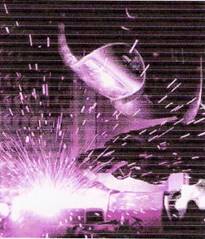
Figure 1 Arc Welding
Many different energy sources can be used for welding, including a gas flame, an electric arc (Fig 1), a laser, an electron beam, friction and ultrasound. While often an industrial process, welding can be done in many different environments, including open air, underwater and in space. Regardless of location, however, welding remains dangerous, and precautions must be taken to avoid burns, electric shock, poisonous fumes, and overexposure to ultraviolet light.
Until the end of the 19th century, the only welding process was forge welding, which blacksmiths had used for centuries to join metals by heating and pounding them. Arc welding and oxyfuel welding were among the first processes to develop late in the century, and resistance welding followed soon after. Welding technology advanced quickly during the early 20th century as World War I and World War II drove the demand for reliable and inexpensive joining methods. Following the wars, several modern welding techniques were developed, including manual methods like shielded metal arc welding; now one of the most popular welding methods, as well as semi-automatic and automatic processes such as gas metal arc welding, submerged arc welding and flux-cored arc welding. Developments continued with the invention of laser beam welding and electron beam welding in the latter half of the century. Today, the science continues to advance. Robot welding is becoming more commonplace in industrial settings, and researchers continue to develop new welding methods and gain greater understanding of weld quality and properties.
Oxy-fuel welding (commonly called oxyacetylene welding) and oxy-fuel cutting are processes that use fuel gases and oxygen to weld and cut metals, respectively. Oxy-fuel is one of the oldest welding processes, though in recent years it has become less popular in industrial applications. French engineers Edmond Fouche and Charles Picard became the first to develop an oxygen-acetylene welding machine in 1903. It is still widely used for welding pipes and tubes, as well as repair work. Oxy-fuel equipment is versatile, lending itself not only to some sorts of iron or steel welding but also to brazing, braze-welding, metal heating (for bending and forming) and for use on sites where there is no power supply.
In oxy-fuel welding, a welding torch is used to weld metals. Welding metal results when two pieces are heated to a temperature that produces a shared pool of molten metal. The molten pool is generally supplied with additional metal called filler. Filler material depends upon the metals to be welded.
In oxy-fuel cutting, a cutting torch is used to heat metal to kindling temperature. A stream of oxygen then trained on the metal combines with the metal which then flows out of the cut (kerf) as an oxide slag.
The manual metal arc process (also know as stick welding) occurs when two wires which form part of an electrical circuit are brought together and then pulled slowly apart, an electric spark is produced across their ends. This spark, or arc as it is called, has a temperature of up to 3,600°C. As the arc is confined to a very small area it can melt metal almost instantly. If one of these wires is connected to the job and the other to a wire rod or electrode, as it is usually called, the heat of the arc melts both the metal of the job and the point of the electrode. The molten metal from the electrode mixes with that from the job and forms the weld.
Metal Active Gas Shielded (MAGS) welding sometimes referred to by its subtypes Gas metal arc welding (GMAW) or metal inert gas (MIG) welding, is a semi-automatic or automatic arc welding process in which a continuous and consumable wire electrode and a shielding gas are fed through a welding gun. A constant voltage, direct current power source is most commonly used with MAGS, but constant current systems, as well as alternating current, can be used.
Originally developed for welding aluminium and other non-ferrous materials in the 1940s, MAGS welding was soon applied to ferrous steels because it allowed for lower welding time compared to other welding processes. The cost of inert gas limited its use in steels until several years later, when the use of semi-inert gases such as carbon dioxide became common. Further developments during the 1950s and 1960s gave the process more versatility and as a result, it became a highly used industrial process. Today, MAGS welding is the most common industrial welding process, preferred for its versatility, speed and the relative ease of adapting the process to robotic automation.
Tungsten Arc Gas-shielded (TAGS) welding, also known as tungsten inert gas (TIG) welding, is an arc welding process that uses a non-consumable tungsten electrode to produce the weld. The weld area is protected from atmospheric contamination by a shielding gas (usually but not always an inert gas such as argon), and a filler metal is normally used, though some welds, known as autogenous welds, do not require it. A constant-current welding power supply produces energy which is conducted across the arc through a column of highly ionized gas and metal vapours known as a plasma.
TAGS welding is most commonly used to weld thin sections of stainless steel and non-ferrous metals such as aluminium, magnesium, and copper alloys. The process grants the operator greater control over the weld than competing procedures such as shielded metal arc welding and gas metal arc welding, allowing for stronger, higher quality welds. However, TAGS welding is comparatively more complex and difficult to master, and furthermore, it is significantly slower than most other welding techniques.
Plasma cutting is a process that is used to cut steel and other metals of different thicknesses (or sometimes other materials) using a plasma torch. In this process, an inert gas (in some units, compressed air) is blown at high speed out of a nozzle; at the same time an electrical arc is formed through that gas from the nozzle to the surface being cut, turning some of that gas to plasma. The plasma is sufficiently hot to melt the metal being cut and moves sufficiently fast to blow molten metal away from the cut.
The heat-affected zone (HAZ) figure 2 is the area of base material, either a metal or a thermoplastic, which has had its microstructure and properties altered by welding or heat intensive cutting operations. The heat from the welding process and subsequent re-cooling causes this change in the area surrounding the weld. The extent and magnitude of property change depends primarily on the base material, the weld filler metal, and the amount and concentration of heat input by the welding process.
The thermal diffusivity of the base material plays a large role—if the diffusivity is high, the material cooling rate is high and the HAZ is relatively small. Alternatively, a low diffusivity leads to slower cooling and a larger HAZ. The amount of heat inputted by the welding process plays an important role as well, as processes like oxy-fuel welding uses high heat input and increase the size of the HAZ. Processes such as TAGS welding where there is much more control over the welding parameters gives a highly concentrated, limited amount of heat, resulting in a small HAZ. Arc welding falls between these two extremes, with the individual processes varying somewhat in heat input.

Fig 2 Cross section through the HAZ of a butt weld
The cross-section illustrated above of a welded butt joint, with the darkest gray representing the weld or fusion zone, the medium gray the heat affected zone, and the lightest gray the base material.
Cutting and welding processes that use intense heat, like oxy-fuel cutting or welding, produce thermal effects near the edge of the cut or weld that lead to microstructural and metallurgical changes in the metal. All thermal cutting and welding processes create an HAZ in the metal.
The changes induced by heat can include:
Some changes, such as heat-tint, are cosmetic and do not matter in some applications. For other applications such as stainless steel, discoloration may matter a great deal. The width of the heat-tint is influenced by the surface condition of the metal. Any surface contaminant or coating, such as paint, oxidation, oil, and even fingerprints, will affect the formation of heat-tint. HAZ width is influenced only by the thermal history of the metal. It is important to remember that the HAZ is not just on the surface but through the depth of the metal.
Other changes to the metal after thermal cutting, like warping or hardening, affect weldability and usefulness of the metal after the thermal cutting. The HAZ may need to be partially or totally removed (by grinding or some other process) before the metal part can be used.
The width of the HAZ from thermal cutting is influenced by:
The International System of Units (SI) defines seven units of measure as a basic set from which all other SI units are derived. These SI base units and their physical quantities are the metre for length, the kilogram for mass, the second for time, the ampere for electrical current, the kelvin for temperature, the candela for luminous intensity, and the mole for the amount of substance.
"The Kelvin, unit of thermodynamic temperature, is the fraction 1/273.16 of the thermodynamic temperature of the triple point of water." 13th CGPM (1967/68, Resolution 4; CR, 104). The Kelvin scale starts at absolute zero which is -273.16 ºC and rises in units called Kelvin which is equal in magnitude to a º Celsius. Therefore, to convert between Kelvin and º Celsius you subtract 273 from a º Celsius to get the Kelvin value or add 273 to a Kelvin temperature to get a º Celsius value.
Health and safety hazards from Thermal processes such as oxy-fuel cutting, welding, and electric welding operations include many of the following:
Exposure to any or all of these can be minimised by using an effective combination of control measures.
When welding or cutting using oxy-fuel equipment of welding plant the operator should be properly trained and supervised and observe all the general safe working procedures required for thermal processes. While this is not meant to be an exhaustive list some specific points to note for Oxy-fuel processes are as follows:
Oxy-Fuel Processes
Electric Welding Processes
Please refer to your instructor for site specific safety requirements before carrying out any welding procedures.

Fig 3 Protective clothing / equipment for Thermal processes
 Root
Root
The position in a prepared butt joint where the parts to be joined are nearest together,
or
In a square butt joint, the edges of the fusion faces which are furthest from the faces of the intended weld,
or
In a fillet weld, the apex of the angle formed by the two fusion faces.
Root Face
 The surface formed by the 'squaring-off' of the root edge of the fusion face to avoid a sharp edge at the root of the preparation.
Root Run
The first run deposited in the root of a joint if there is to be more than one run.
Run
The metal melted or deposited during one passage of the electrode or blow-pipe.
Sealing Run
A small weld deposited on the root side of a butt or corner joint, after completion of the main weld.
Sealing Weld
A weld not-being a strength weld, used to make a fluid-tight joint.
Spatter
Globules of metal thrown out during welding.
Throat Thickness
The shortest distance from the root of the weld to the weld face of a fillet weld,
or
The thickness of weld metal in a butt weld measured at its centre line.
Toe of Weld
The line where the weld face joins the parent metal,
or
The line where the weld face joins the weld face of a previously deposited run.
Weld Face
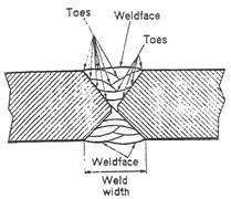 The surface of a weld seen from the side from which the weld was made.
Weld Junction
The boundary between the fusion zone and the heat affected zone.
Weld Metal
All the metal melted during the making of a weld and retained in the weld.
Weld Pool
The pool of liquid metal formed during fusion welding.
Weld Zone
The zone that includes the weld metal, the fusion zone, and the heat-affected zone.
Welding Sequence
The order and direction in which joints, welds, or runs are to be made.

Figures given in this section for bevelling and spacing are suggestions for average work. Exactness of preparation, the size of electrodes and their type, together with the skill of the welder, will influence all dimensions given. In most fabrication shops, such information will be given on the weld procedure and drawings.
The Two Basic Types of Weld
Butt welds over 6 mm thick usually require preparation by bevelling. Figure 3 gives an example of welding plate of 10 mm thickness.
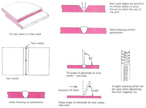
Various Types of Butt Welds or Fillet Welds

A fillet weld is a joint made by two surfaces that meet at right angles. The procedure for fillet and lap welds is shown in illustrations below.
Example Procedure for Welding Plate of 10 mm Thickness

Fillet and Lap Welds
The illustrations below show example test procedures for butt welds and fillet welds respectively.
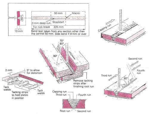
Example Test Procedure for Butt Welds
Example Test Procedure for T-Fillet Welds

Title |
Author |
Ref. Code |
The Induction Book, “Code of Behaviour & Health & Safety Guidelines” |
SOLAS |
|
Basic Welding and Fabrication |
W Kenyon |
ISBN 0-582-00536-L |
Fundamentals of Fabrication and Welding Engineering |
FJM Smith |
ISBN 0-582-09799-1 |
Workshop processes, practices and materials, 3rd edition, Elsevier Science & Technology |
Black, Bruce J 2004 |
ISBN-13: 9780750660730 |
New Engineering Technology |
Lawrence Smyth & Liam Hennessy |
ISBN 086 1674480 |
Source: http://local.ecollege.ie/Content/APPRENTICE/liu/pipefitting/word/M2_U1_Introduction%20to%20thermal%20Process%20and%20Safety.doc
Web site to visit: http://local.ecollege.ie
Author of the text: indicated on the source document of the above text
If you are the author of the text above and you not agree to share your knowledge for teaching, research, scholarship (for fair use as indicated in the United States copyrigh low) please send us an e-mail and we will remove your text quickly. Fair use is a limitation and exception to the exclusive right granted by copyright law to the author of a creative work. In United States copyright law, fair use is a doctrine that permits limited use of copyrighted material without acquiring permission from the rights holders. Examples of fair use include commentary, search engines, criticism, news reporting, research, teaching, library archiving and scholarship. It provides for the legal, unlicensed citation or incorporation of copyrighted material in another author's work under a four-factor balancing test. (source: http://en.wikipedia.org/wiki/Fair_use)
The information of medicine and health contained in the site are of a general nature and purpose which is purely informative and for this reason may not replace in any case, the council of a doctor or a qualified entity legally to the profession.
The texts are the property of their respective authors and we thank them for giving us the opportunity to share for free to students, teachers and users of the Web their texts will used only for illustrative educational and scientific purposes only.
All the information in our site are given for nonprofit educational purposes