
A workpiece which cannot be held between centers because its axis has been drilled or bored, and which is not suitable for holding in a chuck or against a faceplate, is usually machined on a mandrel. A mandrel is a tapered axle pressed into the bore of the workpiece to support it between centers.
A mandrel should not be confused with an arbor, which is a similar device but used for holding tools rather than workpieces. To prevent damage to the work, the mandrel should always be oiled before being forced into the hole. When turning work on a mandrel, feed toward the large end which should be nearest the headstock of the lathe.
A solid machine mandrel is generally made from hardened steel and ground to a slight taper of from 0.0005 to 0.0006 inch per inch. It has very accurately countersunk centers at each end for mounting between centers. The ends of the mandrel are smaller than the body and have machined flats for the lathe dog to grip. The size of the solid machine mandrel is always stamped on the large end of the taper. Since solid machine mandrels have a very slight taper, they are limited to workpieces with specific inside diameters.
An expansion mandrel will accept workpieces having a greater range of sizes. The expansion mandrel is, in effect, a chuck arranged so that the grips can be forced outward against the interior of the hole in the workpiece.

The variety of work that can be performed on the lathe is greatly increased by the use of various lathe attachments. Some lathes come equipped with special attachments; some attachments must be ordered separately. Some common lathe attachments are the steady rest with cathead, the follower rest, the tool post grinding machine, the lathe micrometer stop, the lathe milling fixture, the lathe coolant attachment, the lathe indexing fixture, and the milling-grinding-drilling-slotting attachment (or Versa-Mil). The lathe indexing fixture and Versa-Mil unit are detailed in Chapter 9. Descriptions for the other lathe attachments follows.
Workpieces often need extra support, especially long, thin workpieces that tend to spring away from the tool bit. Three common supports or rests are the steady rest, the cathead, and the follower rest (Figure 7-27).

Steady Rest
The steady rest, also called a center rest, is used to support long workpieces for turning and boring operations. It is also used for internal threading operations where the workpiece projects a considerable distance from the chuck or faceplate. The steady rest is clamped to the lathe bed at the desired location and supports the workpiece within three adjustable jaws. The workpiece must be machined with a concentric bearing surface at the point where the steady rest is to be applied. The jaws must be carefully adjusted for proper alignment and locked in position. The area of contact must be lubricated frequently. The top section of the steady rest swings away from the bottom section to permit removal of the workpiece without disturbing the jaw setting.
Cathead
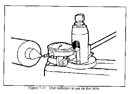
When the work is too small to machine a bearing surface for the adjustable jaws to hold, then a cathead should be used. The cathead has a bearing surface, a hole through which the work extends, and adjusting screws. The adjusting screws fasten the cathead to the work. They are also used to align the bearing surface so that it is concentric to the work axis. A dial indicator must be used to set up the cathead to be concentric and accurate.
Follower Rest
The follower rest has one or two jaws that bear against the workpiece. The rest is fastened to the lathe carriage so that it will follow the tool bit and bear upon the portion of the workpiece that has just been turned. The cut must first be started and continued for a short longitudinal distance before the follower rest may be applied. The rest is generally used only for straight turning and for threading long, thin workpieces. Steady rests and follower rests can be equipped with ball-bearing surfaces on the adjustable jaws. These types of rests can be used without excessive lubricant or having to machine a polished bearing surface.
Micrometer Carriage Stop
The micrometer carriage stop, Figure 7-28, is used to accurately position the lathe carriage. The micrometer stop is designed so the carriage can be moved into position against the retractable spindle of the stop and locked into place. A micrometer gage on the stop enables carriage movement of as little as 0.001 inch. This tool is very useful when facing work to length, turning a shoulder, or cutting an accurate groove.

Tool Post Grinder
The tool post grinder (Figure 7-29) is a machine tool attachment specially designed for cylindrical grinding operations on the lathe. It consists primarily of a 1/4-or 1/3-horsepower electric motor and a wheel spindle connected by pulleys and a belt. The machine fastens to the compound rest of the lathe with a T-slot bolt which fits in the slot of the compound rest in the same manner as the lathe tool post. The tool post grinding machine mounts grinding abrasive wheels ranging from 1/4 inch to 3 or 4 inches in diameter for internal and external grinding operations. The pulleys on the wheel spindle and motor shaft are interchangeable to provide proper cutting speeds for the various wheel sizes. The larger grinding abrasive wheels used for external grinding are attached to the wheel spindle with an arbor. Small, mounted grinding abrasive wheels for internal grinding are fixed in a chuck which screws to the wheel spindle. The electric motor is connected to an electrical power source by a cable and plug. A switch is usually provided at the attachment to facilitate starting and stopping the motor.

Lathe Milling Fixture
This is a fixture designed to provide the ability for limited milling operations. Many repair and fabrication jobs cannot be satisfactorily completed on the standard engine lathe, but with the lathe milling attachment, the small machine shop that is not equipped with a milling machine can mill keyslots, keyways, flats, angles, hex heads, squares, splines, and holes. For specific operating instructions and parts, refer to TM 9-3465-200-10.

In order to properly setup and operate most engine lathes, it is recommended to have the following tools on hand. A machinist tool box with all wrenches, screwdrivers, and common hand tools. A dial indicator may be necessary for some procedures on the lathe. References, charts, tables, and other predetermined data on machine operations may be useful to lathe operators. Keep all safety equipment, along with necessary cleaning marking, and lubricating equipment, in the immediate lathe area to use as needed.
The purposes of using cutting fluids on the lathe are to cool the tool bit and workpiece that are being machined, increase the life of the cutting tool, make a smoother surface finish, deter rust, and wash away chips. Cutting fluids can be sprayed, dripped, wiped, or flooded onto the point where the cutting action is taking place. Generally, cutting fluids should only be used if the speed or cutting action requires the use of cutting fluids. Descriptions of some common cutting fluids used on the lathe follow. Use Table 4-3 in Appendix A for additional information on cutting fluids.
Lard Oil
Pure lard oil is one of the oldest and best cutting oils. It is especially good for thread cutting, tapping, deep hole drilling, and reaming. Lard oil has a high degree of adhesion or oiliness, a relatively high specific heat, and its fluidity changes only slightly with temperature. It is an excellent rust preventive and produces a smooth finish on the workpiece. Because lard oil is expensive, it is seldom used in a pure state but is combined with other ingredients to form good cutting oil mixtures.
Mineral Oil
Mineral oils are petroleum-base oils that range in viscosity from kerosene to light paraffin oils. Mineral oil is very stable and does not develop disagreeable odors like lard oil; however, it lacks some of the good qualities of lard oil such as adhesion, oiliness, and high specific heat. Because it is relatively inexpensive, it is commonly mixed with lard oil or other chemicals to provide cutting oils with desirable characteristics. Two mineral oils, kerosene and turpentine, are often used alone for machining aluminum and magnesium. Paraffin oil is used alone or with lard oil for machining copper and brass.
Mineral-Lard Cutting Oil Mixture
Various mixtures of mineral oils and lard oil are used to make cutting oils which combine the good points of both ingredients but prove more economical and often as effective as pure lard oil.
Sulfurized Fatty-Mineral Oil
Most good cutting oils contain mineral oil and lard oil with various amounts of sulfur and chlorine which give the oils good antiweld properties and promote free machining. These oils play an important part in present-day machining because they provide good finishes on most materials and aid the cutting of tough material.
Soluble Cutting Oils
Water is an excellent cooling medium but has little lubricating value and hastens rust and corrosion. Therefore, mineral oils or lard oils which can be mixed with water are often used to form a cutting oil. A soluble oil and water mix has lubricating qualities dependent upon the strength of the solution. Generally, soluble oil and water is used for rough cutting where quick dissipation of heat is most important. Borax and trisodium phosphate (TSP) are sometimes added to the solution to improve its corrosion resistance.
Soda-Water Mixtures
Salts such as soda ash and TSP are sometimes added to water to help control rust. This mixture is the cheapest of all coolants and has practically no lubricating value. Lard oil and soap in small quantities are sometimes added to the mixture to improve its lubricating qualities. Generally, soda water is used only where cooling is the prime consideration and lubrication a secondary consideration. It is especially suitable in reaming and threading operations on cast iron where a better finish is desired.
White Lead and Lard Oil Mixture
White lead can be mixed with either lard oil or mineral oil to form a cutting oil which is especially suitable for difficult machining of very hard metals.
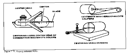
There is relatively little layout work to be done for most lathe work because of the lathe's ability to guide the cutting tool accurately to the workpiece. If center holes must be located and drilled into the end of a workpiece for turning lay out and center-punch the workpiece using other methods. Some suggested methods are to use a bell-type center punch between centers and this cannot be accomplished on the lathe, (Figure 7-32), use hermaphrodite calipers to scribe intersecting arcs, use the centering head of the combination square, or use dividers (Figure 7-33).

Mounting Workpieces in Chucks
When installing the chuck or any attachment that screws onto the lathe headstock spindle, the threads and bearing surfaces of both spindle and chuck must be cleaned and oiled. In cleaning the internal threads of the chuck, a spring thread cleaner is very useful (Figure 7-34).

Turn the spindle so that the key is facing up and lock the spindle in position. Make sure that the spindle and chuck taper are free of grit and chips. Place the chuck in position on the spindle. Engage the draw nut thread and tighten by applying four or five hammer blows on the spanner wrench engaged with the draw nut. Rotate the spindle 180°, engage the spanner wrench, and give four or five solid hammer blows to the spanner wrench handle. The workpiece is now ready for mounting.
Work automatically centers itself in the universal (3 jaw) scroll chuck, drill chuck, collet chucks, and step chuck, but must be manually centered in the independent (4 jaw) chuck. To center work in the independent chuck, line the four jaws up to the concentric rings on the face of the chuck, as close to the required diameter as possible.
Mount the workpiece and tighten the jaws loosely onto the workpiece (Figure 7-35). Spin the workpiece by hand and make approximate centering adjustments as needed, then firmly tighten the jaws.

For rough centering irregularly shaped work, first measure the outside diameter of the workpiece, then open the four jaws of the chuck until the workpiece slides in. Next tighten each opposing jaw a little at a time until the workpiece is held firmly, but not too tightly. Hold a piece of chalk near the workpiece and revolve the chuck slowly with your left hand. Where the chalk touches is considered the high side.
Loosen the jaw opposite and tighten the jaw where the chalk marks are found. Repeat the process until the workpiece is satisfactorily aligned.
To center a workpiece having a smooth surface such as round stock, the best method is to use a dial test indicator. Place the point of the indicator against the outside or inside diameter of the workpiece. Revolve the workpiece slowly by hand and notice any deviations on the dial. This method will indicate any inaccuracy of the centering in thousandths of an inch.
If an irregularly shaped workpiece is to be mounted in the independent chuck, then a straight, hardened steel bar can be used with a dial indicator to align the workpiece. Experienced machinists fabricate several sizes of hardened steel bars, ground with a 60° point, that can be mounted into the drill chuck of the tailstock spindle and guided into the center-punched mark on the workpiece. A dial indicator can then be used to finish aligning the workpiece to within 0.001 inch. If a hardened steel bar is not readily available, a hardened center mounted in the tailstock spindle may be used to align the work while using a dial indicator on the chuck jaws. This method is one of several ways to align a workpiece in an independent chuck. Ingenuity and experience will increase the awareness of the machine operator to find the best method to set up the work for machining.
When removing chucks from the lathe, always use a wooden chuck block under the chuck to support the chuck on the lathe ways. Use care to avoid dropping the chuck on the ways, since this can greatly damage the lathe ways or crush the operator's hands.
Mounting Work to Faceplates
Mount faceplates in the same manner as chucks. Check the accuracy of the faceplate surface using a dial indicator, and true the-faceplate surface by taking a light cut if necessary. Do not use faceplates on different lathes, since this will cause excessive wear of the faceplate due to repeated truing cuts having to be taken. Mount the workpiece using T-bolts and clamps of the correct sizes (Figure 7-36 ). Ensure all surfaces are wiped clean of burrs, chips, and dirt. When a heavy piece of work is mounted off center, such as when using an angle plate, use a counterweight to offset the throw of the work and to minimize vibration and chatter. Use paper or brass shims between the work and the faceplate to protect the delicate surface of the faceplate. After mounting the work to an approximate center location, use a dial indicator to finish accurate alignment.

Mounting Work Between Centers
Before mounting a work-piece between centers, the workpiece ends must be center-drilled and countersunk. This can be done using a small twist drill followed by a 60° center countersink or, more commonly, using a countersink and drill (also commonly called a center drill). It is very important that the center holes are drilled and countersunk so that they will fit the lathe centers exactly. Incorrectly drilled holes will subject the lathe centers to unnecessary wear and the workpiece will not run true because of poor bearing surfaces. A correctly drilled and countersunk hole has a uniform 60° taper and has clearance at the bottom for the point of the lathe center. Figure 7-37 illustrates correctly and incorrectly drilled center holes. The holes should have a polished appearance so as not to score the lathe centers. The actual drilling and countersinking of center holes can be done on a drilling machine or on the lathe itself. Before attempting to center drill using the lathe, the end of the workpiece must be machined flat to keep the center drill from running off center.

Mount the work in a universal or independent chuck and mount the center drill in the lathe tailstock (Figure 7-38). Refer to the section of this chapter on facing and drilling on the lathe, prior to doing this operation. Center drills come in various sizes for different diameters of work (Figure 7-39). Calculate the correct speed and hand feed into the workpiece. Only drill into the workpiece about 2/3 of the body diameter. high speeds and feed them into the work slowly to avoid breaking off the drill point inside the work. If this happens, the work must be removed from the chuck and the point extracted. This is a time-consuming job and could ruin the workpiece.
To mount work between centers, the operator must know how to insert and remove lathe centers. The quality of workmanship depends as much on the condition of the lathe centers as on the proper drilling of the center holes. Before mounting lathe centers in the headstock or tailstock, thoroughly clean the centers, the center sleeve, and the tapered sockets in the headstock and tailstock spindles. Any dirt or chips on the centers or in their sockets will prevent the centers from seating properly and will cause the centers to run out of true.
Install the lathe center in the tailstock spindle with a light twisting motion to ensure a clean fit. Install the center sleeve into the headstock spindle and install the lathe center into the center sleeve with a light twisting motion.
To remove the center from the headstock spindle, hold the pointed end with a cloth or rag in one hand and give the center a sharp tap with a rod or knockout bar inserted through the hollow headstock spindle.
To remove the center from the tailstock, turn the tailstock handwheel to draw the tailstock spindle into the tailstock. The center will contact the tailstock screw and will be bumped loose from its socket.
After mounting the headstock and tailstock centers, the accuracy of the 60° point should be checked using a center gage or a dial indicator. If the center in the headstock is not at 60°, or is scarred and burred, it must be trued while inserted in the lathe headstock spindle. If the headstock center is a soft center (a center that is not heat-treated and hardened), it can be turned true with the lathe tool bit. If the center in the headstock is hardened, it must be ground with a tool post grinding machine to get a true surface (Figure 7-40).

To turn a soft center true with the lathe, first set up the tool bit for right hand turning, center the tool bit; then, rotate the compound rest to an angle of 30° to the axis of the lathe (Figure 7-41). The lathe speed should be set for a finish cut, and the feed is supplied by cranking the handwheel of the compound rest, thus producing a clean and short steep taper with an included angle of 60°. Once trued, the center should stay in place until the operation is completed. If the center must be removed, mark the position on the center and headstock for easy realignment later.

Lathe centers must be parallel with the ways of the lathe in order to turn workpieces straight and true. Before beginning each turning operation, the center alignment should be checked.
The tailstock may be moved laterally to accomplish this alignment by means of adjusting screws after it has been released from the ways. Two zero lines are located at the rear of the tailstock and the centers are approximately aligned when these lines coincide (Figure 7-42). This alignment may be checked by moving the tailstock up close to the headstock so that the centers almost touch, and observing their relative positions (Figure 7-42).

The most accurate method of checking alignment of centers is by mounting the workpiece between centers and taking light cuts at both ends without changing the carriage adjustments. Measure each end of this cut with calipers or a micrometer. If the tailstock end is greater in diameter than the headstock end, the tailstock is moved toward the operator. If the tailstock end is smaller in diameter than the headstock end, the tailstock is moved away from the operator. Take additional cuts in the same manner after each adjustment until both cuts measure the same.
To setup the workpiece between centers on the lathe, a driving faceplate (drive plate) and lathe dog must be used.
(Figure 7-43). Make headstock spindle are faceplate. Screw the sure that the external threads of the clean before screwing on the driving faceplate securely onto the spindle. Clamp the lathe dog on the workpiece so that its tail hangs over the end of the workpiece. If the workpiece is finished, place a shim of soft material such as brass between the setscrew of the dog and workpiece. Mount the workpiece between the centers. Make sure that the lathe dog tail tits freely in the slot of the faceplate and does not bind. Sometimes, the tailstock center is a dead center and does not revolve with the workpiece, so it may require lubrication. A few drops of oil mixed with white lead should be applied to the center before the workpiece is set up. The tailstock should be adjusted so that the tailstock center fits firmly into the center hole of the workpiece but does not bind. The lathe should be stopped at intervals and additional oil and white lead mixture applied to the dead center to prevent overheating harm to the center and the workpiece.

Mounting Work on Mandrels
To machine a workpiece of an odd shape, such as a wheel pulley, a tapered mandrel is used to hold and turn the work. The mandrel must be mounted between centers and a drive plate and lathe dog must be used. The centers must be aligned and the mandrel must be free of burrs. Mount the workpiece onto a lubricated mandrel of the proper size by using an arbor press. Ensure that the lathe dog is secured to the machined flat on the end of the mandrel and not on the smooth surface of the mandrel taper (Figure 7-44). If expansion bushings are to be used with a mandrel, clean and care for the expansion bushings in the same manner as a normal mandrel.

Always feed the tool bit in the direction of the large end of the mandrel, which is usually toward the headstock end, to avoid pulling the work out of the mandrel. If facing on a mandrel, avoid cutting into the mandrel with the tool bit..
General operations on the lathe include straight and shoulder turning, facing, grooving, parting, turning tapers, and cutting various screw threads. Before these operations can be done, a thorough knowledge of the variable factors of lathe speeds, feeds, and depth of cut must be understood. These factors differ for each lathe operation, and failure to use these factors properly will result in machine failure or work damage. The kind of material being worked, the type of tool bit, the diameter and length of the workpiece, the type of cut desired (roughing or finishing), and the working condition of the lathe will determine which speed, feed, or depth of cut is best for any particular operation. The guidelines which follow for selecting speed, feed, and depth of cut are general in nature and may need to be changed as conditions dictate.
Cutting Speeds.
The cutting speed of a tool bit is defined as the number of feet of workpiece surface, measured at the circumference, that passes the tool bit in one minute. The cutting speed, expressed in FPM, must not be confused with the spindle speed of the lathe which is expressed in RPM. To obtain uniform cutting speed, the lathe spindle must be revolved faster for workpieces of small diameter and slower for workpieces of large diameter. The proper cutting speed for a given job depends upon the hardness of the material being machined, the material of the tool bit, and how much feed and depth of cut is required. Cutting speeds for metal are usually expressed in surface feet per minute, measured on the circumference of the work. Spindle revolutions per minute (RPM) are determined by using the formula:
![]()
Which is simplified to:
![]()
Where SFM is the rated surface feet per minute, also expressed as cutting speed.
RPM is the spindle speed in revolutions per minute
D is the diameter of the work in inches.
In order to use the formula simply insert the cutting speed of the metal and the diameter of the workpiece into the formula and you will have the RPM.
Turning a one-half inch piece of aluminum, cutting speed of 200 SFM, would result in the following:

Table 7-2 in Appendix A lists specific ranges of cutting speeds for turning and threading various materials under normal lathe conditions, using normal feeds and depth of cuts. Note that in Table 7-2 the measurement calculations are in inch and metric measures. The diameter measurements used in these calculations are the actual working diameters that are being machined, and not necessarily the largest diameter of the material. The cutting speeds have a wide range so that the lower end of the cutting speed range can be used for rough cutting and the higher end for finish cutting. If no cutting speed tables are available, remember that, generally, hard materials require a slower cutting speed than soft or ductile materials. Materials that are machined dry, without coolant, require a slower cutting speed than operations using coolant. Lathes that are worn and in poor condition will require slower speeds than machines that are in good shape. If carbide-tipped tool bits are being used, speeds can be increased two to three times the speed used for high-speed tool bits.
Feed
Feed is the term applied to the distance the tool bit advances along the work for each revolution of the lathe spindle. Feed is measured in inches or millimeters per revolution, depending on the lathe used and the operator's system of measurement. Table 7-3 in Appendix A is a guide that can be used to select feed for general roughing and finishing operations. A light feed must be used on slender and small workpieces to avoid damage. If an irregular finish or chatter marks develop while turning, reduce the feed and check the tool bit for alignment and sharpness. Regardless of how the work is held in the lathe, the tool should feed toward the headstock. This results in most of the pressure of the cut being put on the work holding device. If the cut must be fed toward the tailstock, use light feeds and light cuts to avoid pulling the workpiece loose.
Depth of Cut
Depth of cut is the distance that the tool bit moves into the work, usually measured in thousandths of an inch or in millimeters. General machine practice is to use a depth of cut up to five times the rate of feed, such as rough cutting stainless steel using a feed of 0.020 inch per revolution and a depth of cut of 0.100 inch, which would reduce the diameter by 0.200 inch. If chatter marks or machine noise develops, reduce the depth of cut.
Graduated micrometer collars can be used to accurately measure this tool bit movement to and away from the lathe center axis. Thus, the depth of cut can be accurately measured when moving the tool bit on the cross slide by using the cross slide micrometer collar. The compound rest is also equipped with a micrometer collar. These collars can measure in inches or in millimeters, or they can be equipped with a dual readout collar that has both. Some collars measure the exact tool bit movement, while others are designed to measure the amount of material removed from the workpiece (twice the tool bit movement). Consult the operator's instruction manual for specific information on graduated collar use.

Facing is machining the ends and shoulders of a piece of stock smooth, flat, and perpendicular to the lathe axis. Facing is used to cut work to the desired length and to produce a surface from which accurate measurements may be taken.
Facing Work in a Chuck
Facing is usually performed with the work held in a chuck or collet. Allow the workpiece to extend a distance no more than 1 1/2 times the work diameter from the chuck jaws, and use finishing speeds and feeds calculated using the largest diameter of the workpiece. The tool bit may be fed from the outer edge to the center or from the center to the outer edge. Normal facing is done from the outer edge to the center since this method permits the operator to observe the tool bit and layout line while starting the cut. This method also eliminates the problem of feeding the tool bit into the solid center portion of the workpiece to get a cut started.. Use a left-hand finishing tool bit and a right-hand tool holder when facing from the outer edge toward the center. Work that has a drilled or bored hole in the center may be faced from the center out to the outer edge if a right-hand finishing tool bit is used. Avoid excessive tool holder and tool bit overhang when setting up the facing operation. Set the tool bit exactly on center to avoid leaving a center nub on the workpiece (Figure 7-46 ). Use the tailstock center point as a reference point when setting the tool bit exactly on center. If no tailstock center is available, take a trial cut and readjust as needed. If using the cross slide power feed to move the tool bit (into the center), disengage power when the tool bit is within l/16 inch of the center and finish the facing cut using hand feed.

Facing Work Between Centers
Sometimes the workpiece will not fit into a chuck or collet, so facing must be done between centers. To properly accomplish facing between centers, the workpiece must be center-drilled before mounting into the lathe. A half male center (with the tip well lubricated with a white lead and oil mixture) must be used in the lathe tailstock to provide adequate clearance for the tool bit. The tool bit must be ground with a sharp angle to permit facing to the very edge of the center drilled hole (Figure 7-47). Start the facing cut at the edge of the center-drilled hole after checking for tool bit clearance, and feed the cutting tool out to the edge. Use light cuts and finishing feeds, which will reduce the tension put on the half male center. Replace the half male center with a standard center after the facing operation, since the half male center will not provide adequate support for general turning operations. Only a small amount of material can be removed while facing between centers. If too much material is removed, the center-drilled hole will become too small to support the workpiece.

Precision Facing
Special methods must be used to face materials to a precise length. One method is to mount the work in a chuck and lightly face one end with a cleanup cut. Then, reverse the stock and face it to the scribed layout line. This method may not be as accurate as other methods, but it will work for most jobs. A more precise method to face a piece of stock to a specified length is to turn the compound rest to an angle of 30 degrees to the cross slide and then use the graduated micrometer collar to measure tool bit movement, Figure 7-48. At this angle of the compound rest, the movement of the cutting tool will always be half of the reading of the graduated collar. Thus, if the compound rest feed is turned 0.010 inch, the tool bit will face off 0.005 inch of material. With the compound rest angled at 30°, a light cut may be made on the first end, then the piece reversed and faced to accurate length. Always lock the carriage down to the bed. This provides the most secure and accurate base for the cutting tool and helps eliminate unwanted vibration during facing operations. Another way to face to a precise length is to use the lathe carriage micrometer stop to measure the carriage and tool bit movement. Using the micrometer stop can sometimes be faster and easier than using the compound rest graduated collar for measuring tool bit movement.

Straight turning, sometimes called cylindrical turning, is the process of reducing the work diameter to a specific dimension as the carriage moves the tool along the work. The work is machined on a plane parallel to its axis so that there is no variation in the work diameter throughout the length of the cut. Straight turning usually consists of a roughing cut followed by a finishing cut. When a large amount of material is to be removed, several roughing cuts may need to be taken. The roughing cut should be as heavy as the machine and tool bit can withstand. The finishing cut should be light and made to cut to the specified dimension in just one pass of the tool bit. When using power feed to machine to a specific length, always disengage the feed approximately 1/16-inch away from the desired length dimension, and then finish the cut using hand feed.
Setting Depth of Cut
In straight turning, the cross feed or compound rest graduated collars are used to determine the depth of cut, which will remove a desired amount from the workpiece diameter. When using the graduated collars for measurement, make all readings when rotating the handles in the forward direction. The lost motion in the gears, called backlash, prevents taking accurate readings when the feed is reversed. If the feed screw must be reversed, such as to restart a cut, then the backlash must be taken up by turning the feed screw handle in the opposite direction until the movement of the screw actuates the movement of the cross slide or compound rest. Then turn the feed screw handle in the original or desired direction back to the required setting.
Setting Tool Bit for Straight Turning
See Figure 7-49. For most straight turning operations, the compound rest should be aligned at an angle perpendicular to the cross slide, and then swung 30° to the right and clamped in position. The tool post should be set on the left-hand side of the compound rest T-slot, with a minimum of tool bit and tool holder overhang.

When the compound rest and tool post are in these positions, the danger of running the cutting tool into the chuck or damaging the cross slide are minimized. Position the roughing tool bit about 5° above center height for the best cutting action. This is approximately 3/64-inch above center for each inch of the workpiece diameter. The finishing tool bit should be positioned at center height since there is less torque during finishing. The position of the tool bit to the work should be set so that if anything occurs during the cutting process to change the tool bit alignment, the tool bit will not dig into the work, but instead will move away from the work. Also, by setting the tool bit in this position, chatter will be reduced. Use a right-hand turning tool bit with a slight round radius on the nose for straight turning. Always feed the tool bit toward the headstock unless turning up to an inside shoulder. Different workpieces can be mounted in a chuck, in a collet, or between centers. Which work holding device to use will depend on the size of the work and the particular operation that needs to be performed.
Turning Work Between Centers
Turning work that is held between centers is one accurate method that is available. The chief advantage of using this method is that the work can be removed from the lathe and later replaced for subsequent machining operations without disturbing the trueness of the turned surface in relation to the center holes of the workpiece. The lathe centers must be in good condition and carefully aligned if the turning operation is to be accurate. If necessary, true the centers and realign as needed. After the workpiece is center-drilled, place a lathe dog (that is slightly larger in diameter than the workpiece) on the end of the work that will be toward the headstock, and tighten the lathe dog bolt securely to the workpiece). If using a dead center in the tailstock, lubricate the center with a mixture of white lead and motor oil. A ball bearing live center is best for the tailstock center since this center would not need lubrication and can properly support the work. Extend the tailstock spindle out about 3 inches and loosen the tailstock clamp-down nut. Place the work with the lathe dog end on the headstock live center and slide the tailstock forward until the tailstock center will support the work; then, secure the tailstock with the clamp-down nut. Adjust the tail of the lathe dog in the drive plate slot, making sure that the tail does not bind into the slot and force the work out of the center. A good fit for the lathe dog is when there is clearance at the top and bottom of the drive plate slot on both sides of the lathe dog tail. Tension should be applied to hold the work in place, but not so much tension that the tail of the lathe dog will not move freely in the drive -plate slot.
Check tool bit clearance by moving the tool bit to the furthest position that can be cut without running into the lathe dog or the drive plate. Set the lathe carriage stop or micrometer carriage stop at this point to reference for the end of the cut and to protect the lathe components from damage. Set the speed, feed, and depth of cut for a roughing cut and then rough cut to within 0.020 inch of the final dimension. Perform a finish cut, flip the piece over, and change the lathe dog to the opposite end. Then rough and finish cut the second side to final dimensions.
Turning Work in Chucks
Source: http://faculty.ksu.edu.sa/hossainy/Book1/Chapter%207.doc
Web site to visit:http://faculty.ksu.edu.sa
Author of the text: indicated on the source document of the above text
If you are the author of the text above and you not agree to share your knowledge for teaching, research, scholarship (for fair use as indicated in the United States copyrigh low) please send us an e-mail and we will remove your text quickly. Fair use is a limitation and exception to the exclusive right granted by copyright law to the author of a creative work. In United States copyright law, fair use is a doctrine that permits limited use of copyrighted material without acquiring permission from the rights holders. Examples of fair use include commentary, search engines, criticism, news reporting, research, teaching, library archiving and scholarship. It provides for the legal, unlicensed citation or incorporation of copyrighted material in another author's work under a four-factor balancing test. (source: http://en.wikipedia.org/wiki/Fair_use)
The information of medicine and health contained in the site are of a general nature and purpose which is purely informative and for this reason may not replace in any case, the council of a doctor or a qualified entity legally to the profession.
The texts are the property of their respective authors and we thank them for giving us the opportunity to share for free to students, teachers and users of the Web their texts will used only for illustrative educational and scientific purposes only.
All the information in our site are given for nonprofit educational purposes