What is a microcontroller?
A microcontroller is often described as a ‘computer-on-a-chip’. Microcontrollers have a controller and memory all built into a single chip. As they are small and inexpensive they can easily be built into other devices to make these products more intelligent and easier to use.
Microcontrollers are usually programmed for a specific electronic product - for instance, a microwave oven may use a single microcontroller to process information from the keypads, display user information on the seven-segment display or control the output devices (turntable motor, light, bell and magnetron).
Microcontrollers are single-chip ‘computers’ designed to control specific processes or products. The microcontroller is programmed with a program to complete the desired task. By altering this program, the same ‘brand’ of microcontroller can be used to complete different tasks. The same microcontroller device can therefore be used in a range of different products by simply programming it with a different program.
One microcontroller can often replace a number of separate parts, or even a complete electronic circuit. Some of the advantages of using microcontrollers in a product design are:
Applications that use microcontrollers include household appliances (for example a microwave), alarm systems (for example a fire alarm), medical equipment (for example an incubator for premature babies) and electronic equipment (for example a computer mouse).
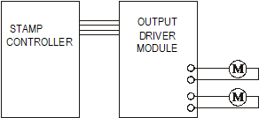
The Stamp Controller
The stamp controller system consists of three main components.
This software runs on a computer and allows you to use the computer keyboard to type in programs.
This is the cable that connects the computer to the stamp controller. The cable needs to be connected only when downloading programs. It does not have to be connected when the stamp controller is running because the program is stored on the stamp controller board – even when the power supply is removed!
Flowcharts
Flowcharts are commonly used to explain how a program works. As flowcharts are drawn graphically they often make programs easier to understand. A flowchart should be drawn for each program you develop.
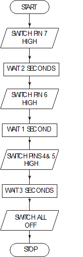
A simple flowchart is shown below.
You work through the flow chart from top to bottom

The flowchart shown uses three different symbols.
Start/stop symbol
The ‘Start’ or ‘Stop’ symbol shape is a rectangle with rounded ends. Each flowchart must contain only one ‘Start’ symbol and, usually, only one ‘Stop’ symbol.
Wait symbol
The ‘Wait’ symbol is a rectangle. The text inside the symbol explains how long the time delay is.
Outputs symbol
The ‘Outputs’ symbol is a parallelogram. The text inside the symbol explains which output pins are switched on or off at any time.
Converting a flowchart into a control program
Once a flowchart has been drawn it is necessary to convert it into the stamp controller programming language, which is called PBASIC.
A PBASIC program for the flowchart shown on the previous page is:
main:
![]()
![]()
![]()
![]()
![]() high 5 ' switch pin 5 on
high 5 ' switch pin 5 on
high 4 ' switch pin 4 on
![]()
![]() low 7 ' switch pin 7 off
low 7 ' switch pin 7 off
low 6 ' switch pin 6 off
low 5 ' switch pin 5 off
low 4 ' switch pin 4 off
![]()
Note that some flowchart symbols require more than one line of PBASIC code. Also remember that comments (an explanation after the apostrophe (') symbol) make each line of a PBASIC program much easier to understand. These comments are ignored by the computer when it downloads a program to the stamp controller.
A label (for example ‘main:’ in the program above) can be any word (apart from keywords such as ‘high’), but it must begin with a letter. When the label is first defined it must end with a colon (:). The colon ‘tells’ the computer that the word is a new label.
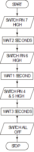
Continuous loops Flowcharts

This line leads the end of the flowchart back to the start, so that as soon as it finishes, it goes back to the start again. Use arrows to show direction

A PBASIC program that would achieve this control operation is listed below.
main:
high 7 ' switch pin 7 on
pause 2000 ' wait for 2 seconds
high 6 ' switch pin 6 on
pause 1000 ' wait for 1 second
high 5 ' switch pin 5 on
high 4 ' switch pin 4 on
pause 3000 ' wait for 3 seconds
low 7 ' switch pin 7 off
low 6 ' switch pin 6 off
low 5 ' switch pin 5 off
low 4 ' switch pin 4 off
pause 1000 ' wait for 1 second
goto main ' jump back to start
Using symbols
Sometimes it can be hard to remember which pins are connected to which devices. The ‘symbol’ command can then be used at the start of a program to rename the inputs and outputs.
symbol red = 7 ' rename 7 ‘red’
symbol green = 5 ' rename 5 ‘green’
main: ' make a label called ‘main’
high red ' red LED on
low green ' green LED off
pause 1000 ' wait 1 second
low red ' red LED off
high green ' green LED on
pause 1000 ' wait 1 second
goto main ' jump back to the start
Inside a Microcontroller
The ‘brain’ of the stamp controller system is the 18-pin microcontroller in the centre of the board. Although microcontrollers are relatively cheap (some microcontrollers cost less than £1), they are very complex devices containing many thousands of transistors, resistors and other electronic components. The microcontroller on the stamp controller has been programmed to read the commands from the EEPROM memory chip and then carry these commands out.
The main features of the microcontroller are shown in the block diagram.

Microcontrollers contain all of these features within a single package, as opposed to microprocessor systems (for example as used in desktop computers), where each block in the diagram above is normally a separate integrated circuit. In general the only component that needs to be added to a microcontroller is a clock resonator, which sets the operating speed of the microcontroller.
Microcontrollers contain both ROM (permanent memory) and RAM (temporary memory).
The ROM (Read Only Memory) contains the operating instructions (that is, the ‘program’) for the microcontroller. The ROM is ‘programmed’ before the microcontroller is installed in the target system, and the memory retains the information even when the power is removed.
The EEPROM (Electronically Erasable and Programmable Read Only Memory). Is used on the stamp board. This is ROM, which can be changed by writing a new program to it.
The RAM (Random Access Memory) is ‘temporary’ memory used for storing information whilst the program is running. This is normally used to store answers to mathematical ‘sums’ the microcontroller carries out as it is working. This memory is ‘volatile’, which means that as soon as the power is disconnected the contents of the memory are lost.
The processing unit (full name arithmetic and logic unit (ALU)) is the ‘control centre’ of the microcontroller. It operates by reading instructions from the ROM and then carrying out the mathematical operations for each instruction. The speed at which these operations occur is controlled by the clock circuit.
The clock circuit within the microcontroller ‘synchronises’ all the internal blocks (ALU, ROM, RAM, etc.) so that the whole system works correctly.
Buses
Information is carried between the various blocks of the microcontroller along ‘groups’ of wires called buses. The ‘data bus’ carries data between the ALU and RAM, and the ‘program bus’ carries the program instructions from the ROM to the ALU.
 The stamp controller can only drive low-power devices, such as LEDs, directly. It cannot drive devices such as lamps, buzzers, solenoids or motors directly because these devices require a higher current to operate.
A common way to drive these devices is with a transistor, as shown in the diagram above. In this case the lamp is controlled by the transistor switching on and off.

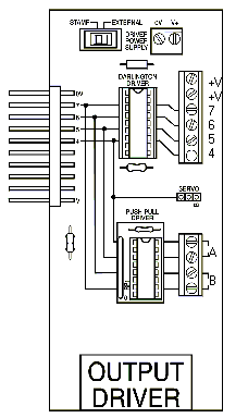
The output driver module provides four transistor outputs, as in the circuit shown above. Instead of using four separate transistors, the output driver uses an integrated circuit called the ULN2803A, which contains all the transistors in one 18-pin ‘chip’.

To use the transistor outputs, the output device should be connected between the screw-terminal numbered output (4–7) and a V+ connection. The positive (red) wire on polarised devices (for example a buzzer) should be connected to the V+ connection.
The white 6-pin header beside the screw terminals allows a ‘stepper motor’ or control model to be connected easily to all four of the outputs.
This could have been a motor, or a buzzer
This wire could have been connected to 7, 6, 5 or 4. As long as the correct pin was switched high or low in the program.
Connect a bulb to the output driver module as shown in the diagram.
The ‘high’ and ‘low’ commands can be used to switch the output pins on and off
main: ' make a label called ‘main’
high 7 ' switch on bulb
pause 1000 ' wait 1 second
low 7 ' switch off bulb
pause 1000 ' wait 1 second
high 7 ' switch on bulb
pause 1000 ' wait 1 second
low 7 ' switch off bulb
pause 1000 ' wait 1 second
high 7 ' switch on bulb
pause 1000 ' wait 1 second
low 7 ' switch off bulb
pause 1000 ' wait 1 second
goto main ' jump back to the start
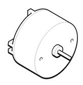
Speed control of d.c. motors

There are two ways to control the speed of a d.c. motor. The simplest is to vary the voltage applied to the motor. If, for instance, 3 V is applied to a small d.c. motor it will rotate at a lower speed than if 5 V were applied. Unfortunately the ‘turning power’ (torque) of the motor will also drop, which means the whole motor system will be less powerful.
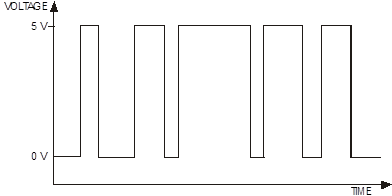
The second way to control the motor is to always apply the full voltage (for example
5 V) across the motor, but then to switch the power supply on and off rapidly. As the power supply is off some of the time, the motor does not receive as much power and so the motor turns more slowly. The advantage of this system is that the torque remains quite high.
This system is called pulse-width modulation (PWM). The time that the power supply is switched on is called the mark time, and the time that the motor is switched off is called the space time. By varying the on (mark)-to-off (space) ratio, the speed of the motor can be varied.

The previous system has a major draw back for controlling motors.
It will only allow them to turn in 1 direction.
In many applications we need to control the motor in both directions

The output driver module also contains a second integrated circuit called the L293D push-pull driver. This chip allows forward and reverse control of two d.c. motors. Each motor output uses two of the stamp controller output pins to control the direction of rotation of the motor.
Pin 4 |
Pin 5 |
Motor A |
|
Pin 6 |
Pin 7 |
Motor B |
off |
off |
halt |
|
off |
off |
halt |
off |
on |
forwards |
|
off |
on |
forwards |
on |
off |
backwards |
|
on |
off |
backwards |
on |
on |
halt |
|
on |
on |
halt |
To use the push-pull motor output, the motor should be connected between the screw terminals labelled A or B. If the motor turns in the opposite direction to that expected, the two motor wires should be swapped over.
Some d.c. motors create electrical noise as they rotate. This problem only occurs with some d.c. motors - it is not normally a problem with d.c. solar motors. This electrical noise can affect the stamp controller, sometimes causing it to reset and act erratically. Fortunately this problem is very easily solved by connecting a 220 mF polyester capacitor directly across the motor terminals. The capacitor smoothes out the electrical noise before it can affect the stamp controller.
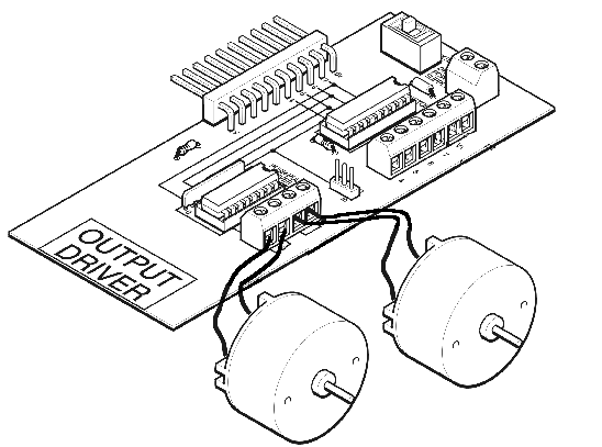
Connect two motors to the output driver module as shown in the diagram.
The ‘high’ and ‘low’ commands can be used to switch the output pins and control the motors forward, backward and halt.
main: ' make a label called ‘main’
high 5 ' motor A forward
high 7 ' motor B forward
pause 1000 ' wait 1 second
low 5 ' motor A halt
low 7 ' motor B halt
pause 1000 ' wait 1 second
high 4 ' motor A backward
high 6 ' motor B backward
pause 1000 ' wait 1 second
low 4 ' motor A halt
low 6 ' motor B halt
goto main ' jump back to the start
‘For … next’ loops


main: for counter = 1 to 5 ' start a for … next loop
high 7 ' switch pin 7 high
pause 1000 ' wait for 1 second
low 7 ' switch pin 7 low
pause 1000 ' wait for 1 second
next counter ' end of for … next loop
end ' end program
We set the number of times we want to loop here

It is often useful to repeat the same part of a program a number of times, for instance when flashing an LED. In these cases a ‘for … next’ loop can be used.
In this flowchart the LED connected to output pin 7 is flashed on and off five times. The number of times the code has been repeated is stored - that is, stored in the RAM memory of the stamp controller. There are 10 available variables, labelled b0 to b9, which can be used in this way. These variables can also be renamed using the symbol command to make them easier to remember.
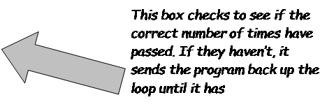
Sub-procedures
A sub-procedure is a separate ‘mini-program’ that can be called from the main program. Once the sub-procedure has been carried out, the main program continues.
Sub-procedures are often used to separate the program into small sections to make it easier to understand. Sub-procedures that complete common tasks can also be copied from program to program to save time.
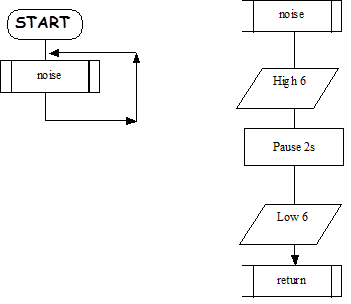
The following program uses a sub-procedures (‘noise’).
main: ' make a label called ‘main’
gosub noise ' call the sub-procedure noise
goto main ' loop back
end ' end of the main program
noise:
high 6 ' buzzer on
pause 2000 ' wait 2 seconds
low 6 ' buzzer off
return ' return from the sub-procedure
When the gosub command is used it send the computer to the appropriate place in the program. That sub procedure must end with return
Using Inputs

A digital sensor is a simple ‘switch’ type sensor that can only be ‘on’ or ‘off’.
Common examples of a digital sensor are:
The simplest type of switch is represented by the symbol shown below.
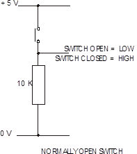
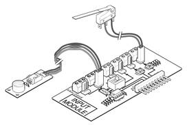
The input module provides the interfacing circuits required to connect switches and sensors to the stamp controller.
When the slide switch on the input module is ‘up’ the input module provides four digital (on/off) switch connections. These can be used to connect input switches (for example a microswitch) to the stamp controller. The switches can be connected through the screw-terminal blocks or through the white push-on headers.
Input pins 0 and 1 have ‘on-board’ test switches. These allow programs to be tested without the need to connect external switches.
Including digital inputs in flowcharts and programs
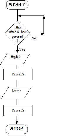
main: if pin 0 = 1 then lights
goto main
lights: high 7
pause 2000
low 7
pause 2000
end
Section 5: Number systems
The first sixteen numbers in the decimal and binary systems are shown in the table below.
|
Decimal |
Binary |
|
0 |
0000 |
|
1 |
0001 |
|
2 |
0010 |
|
3 |
0011 |
|
4 |
0100 |
|
5 |
0101 |
|
6 |
0110 |
|
7 |
0111 |
|
8 |
1000 |
|
9 |
1001 |
|
10 |
1010 |
|
11 |
1011 |
|
12 |
1100 |
|
13 |
1101 |
|
14 |
1110 |
|
15 |
1111 |
A single binary digit is referred to as a bit (binary digit). Different systems carry out calculations using different numbers of bits, and so systems are often referred to as 8-bit, 16-bit or 32-bit systems. The most common microcontrollers use the 8-bit system, although 32-bit microcontrollers are also now becoming more readily available.
When using a number of different counting systems it is important to distinguish which counting system you are using. For instance, the number ‘10’ has different values in the decimal and binary counting systems!
Therefore the following notations are used with stamp controller programs.
Decimal values are written as usual: 10 (= 10 in decimal)
Binary values are indicated by a % symbol: %10 (= 2 in decimal)
Eight bits grouped together are described as a byte. The decimal value of a byte is calculated by adding together the corresponding decimal value of each of the individual bits. The eight bits in a byte are labelled bits 0 to 7, from right to left. The rightmost bit is called the least significant bit (LSB) and the leftmost bit is called the most significant bit (MSB). The decimal value of each bit is given in the table below.
bit number |
7 |
6 |
5 |
4 |
3 |
2 |
1 |
0 |
decimal value |
128 |
64 |
32 |
16 |
8 |
4 |
2 |
1 |
The binary number %10010111 when converted into decimal would be:
1 |
x |
128 |
= |
128 |
0 |
x |
64 |
= |
0 |
0 |
x |
32 |
= |
0 |
1 |
x |
16 |
= |
16 |
0 |
x |
8 |
= |
0 |
1 |
x |
4 |
= |
4 |
1 |
x |
2 |
= |
2 |
1 |
x |
1 |
= |
1 |
|
|
|
Total: |
151 |
Note that when writing binary numbers it is quite common to write all eight bits, even if the first bits are equal to zero (unlike the decimal system, where leading zeros are not normally written).
To convert any decimal number into binary, repeatedly divide the decimal number by two and record the remainder after each division. The binary number is then found by reading up the remainder column. The decimal number 29 is used as an example.
29 |
÷ |
2 |
= |
14 |
rem. 1 |
14 |
÷ |
2 |
= |
7 |
rem. 0 |
7 |
÷ |
2 |
= |
3 |
rem. 1 |
3 |
÷ |
2 |
= |
1 |
rem. 1 |
1 |
÷ |
2 |
= |
0 |
rem. 1 |
Therefore the decimal number 29 equals the binary number %00011101

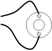
Stepper motors are very accurate motors that are commonly used in computer disc- drives, printers, X–Y plotters and clocks. Unlike d.c. motors, which spin round freely when power is applied, stepper motors require that their power supply is continuously ‘pulsed’ in four different patterns. For each pulse, the stepper motor moves around one ‘step’, typically 7.5 degrees (giving 48 steps in a full revolution).
Stepper motors do have some limitations. First, the power consumption is greatest when the stepper motor is stopped (as all coils are still energised). The speed of revolution is also limited to around 100 steps per second, which provides a rotational speed of 2 revolutions per second or 120 revolutions per minute.
The stepper motor contains magnets that are fixed to the central armature. Four electronic coils are located around the casing. When a current is passed through these coils they generate a magnetic field, which attracts/repels the permanent magnets on the armature, and so the armature spins one ‘step’ until the magnetic fields align. The coils are then energised in a different pattern to create a different magnetic field, and the armature spins another step.
To make the armature rotate continuously, the four coils inside the stepper motor must be switched on and off in a certain step order. The ULN2803A driver chip on the output driver module provides the method of interfacing these four coils.
The table below shows the four different steps required to make the motor turn.
Step |
Coil 4 |
Coil 3 |
Coil 2 |
Coil 1 |
1 |
1 |
0 |
1 |
0 |
2 |
1 |
0 |
0 |
1 |
3 |
0 |
1 |
0 |
1 |
4 |
0 |
1 |
1 |
0 |
1 |
1 |
0 |
1 |
0 |
To make the motor spin the other way, the steps are reversed (i.e. 4-3-2-1-4, etc. rather than 1-2-3-4-1, etc.).
The wiring configuration of stepper motors varies between different manufacturers. Therefore, it may be necessary to rearrange the coil connections for the above sequence to operate correctly. An incorrect coil arrangement will result in the stepper motor vibrating back and forth rather than rotating.
The sequence of wires for the Middlesex Stepper Motor is, from the top:
white, white, blue, yellow, brown, red and you may have to change the wires on these stepper motors to get this sequence.
A typical program to make a stepper motor spin continuously is shown below;
symbol delay = b0 ' define the variable
init: let dirs = %11110000 ' make pins 4-7 outputs
let delay = 100 ' set delay to 100ms
main: let pins = %10100000 ' first step
pause delay ' pause for delay
let pins = %10010000 ' second step
pause delay ' pause for delay
let pins = %01010000 ' third step
pause delay ' pause for delay
let pins = %01100000 ' fourth step
pause delay ' pause for delay
goto main ' loop forever
Analogue sensors

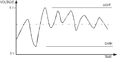
An analogue sensor measures a continuous property such as light, temperature or position. The analogue sensor provides a varying voltage signal. This voltage signal can be represented by a number in the range 1 to 240 (for example very dark = 1, bright light = 240).
|
Common examples of an analogue sensor are:
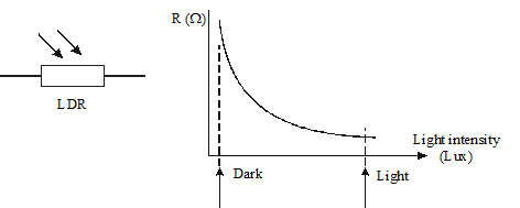
The LDR is a component whose resistance depends on the amount of light falling on it. Its resistance changes with light level. In bright light the LDR’s resistance is low (typically around 1 kW). In darkness its resistance is high (typically around 1 MW).
|
The circuit symbol and a graph showing the resistance at various light levels are shown below.
The analogue sensors are connected to the input module in a potential divider arrangement.

The thermistor is a component whose resistance depends on its temperature.
The circuit symbol and a graph showing the resistance at various temperatures.
|
A variable resistor is used to measure position.


The input module provides the interfacing circuits required to connect switches and sensors to the stamp controller.
When the slide switch is ‘down’ the input module provides two digital (on/off) and two analogue sensor connections.
The two analogue sensor connections allow the connection of analogue sensors (for example an LDR light sensor or a thermistor temperature sensor). The analogue sensors provide a reading in the range of 1–240 with a change in value (of, for example, the light level or temperature).
Including analogue inputs in flowcharts and programs

main: if sensorA > 100 then lights
 goto main
lights: high 7
pause 2000
low 7
pause 2000
end
This number can be anywhere between 0 and 255. If this was a light sensing system, you could set exactly the light level you wanted it to switch on at by changing this number
Source: http://www.earlstonhigh.scotborders.sch.uk/learningzone/technical/Revision%20Notes/SGTS%20Revision%20Notes/6-Programmable%20Control.doc
Web site to visit: http://www.earlstonhigh.scotborders.sch.uk
Author of the text: indicated on the source document of the above text
If you are the author of the text above and you not agree to share your knowledge for teaching, research, scholarship (for fair use as indicated in the United States copyrigh low) please send us an e-mail and we will remove your text quickly. Fair use is a limitation and exception to the exclusive right granted by copyright law to the author of a creative work. In United States copyright law, fair use is a doctrine that permits limited use of copyrighted material without acquiring permission from the rights holders. Examples of fair use include commentary, search engines, criticism, news reporting, research, teaching, library archiving and scholarship. It provides for the legal, unlicensed citation or incorporation of copyrighted material in another author's work under a four-factor balancing test. (source: http://en.wikipedia.org/wiki/Fair_use)
The information of medicine and health contained in the site are of a general nature and purpose which is purely informative and for this reason may not replace in any case, the council of a doctor or a qualified entity legally to the profession.
The texts are the property of their respective authors and we thank them for giving us the opportunity to share for free to students, teachers and users of the Web their texts will used only for illustrative educational and scientific purposes only.
All the information in our site are given for nonprofit educational purposes