
Classification of IC engine: Normally IC engines are classified into 1.C.I engines and 2.S.I engines
Some of the important classifications are given below,
1. Number of strokes -two stroke and four stroke 2. Working Cycles -Otto ,Diesel, Dual cycle 3. Cylinder arrangement -In-line, V-type, Opposed, Radial 4. Valve Arrangement -T-head, F-head, L-head, I-head 5. Fuel Used -Petrol, Diesel, Gas 6. Combustion chamber design -Open, divided 7. Cooling System -Water and air cooling 8. According to the number of cylinders -Single and Multi 9. According to the speed -Slow, medium, and high speed engines 10. According to the application -Stationary, Automotive, Marine, Locomotive, Aircraft etc.,
The cylinder block is the main body of the engine, the structure that supports all the other components of the engine. In the case of the single cylinder engine the cylinder block houses the cylinder, while in the case of multi-cylinder engine the number of cylinders are cast together to form the cylinder block. The cylinder head is mounted at the top of the cylinder block. When the vehicle runs, large amounts of heat are generated within the cylinder block. To remove this heat the cylinder block and the cylinder head are cooled by water flowing through the water jackets within larger engines such as those found in cars and trucks. For smaller vehicles like motorcycles, fins are provided on the cylinder block and on the cylinder head to cool them. The bottom portion of the cylinder block is called a crankcase. Within the crankcase is where lubricating oil, which is used for lubricating various moving parts of the engine, is stored. 2) Cylinder: As the name suggests it is a cylindrical shaped vessel fitted in the cylinder block. This cylinder can be removed from the cylinder block and machined whenever required to. It is also called a liner or sleeve. Inside the cylinder the piston moves up and down, which is called the reciprocating motion of the piston. Burning of fuel occurs at the top of the cylinder, due to which the reciprocating motion of the piston is produced. The surface of the cylinder is finished to a high finish, so that there is minimal friction between the piston and the cylinder. 3) Piston: The piston is the round cylindrical component that performs a reciprocating motion inside the cylinder. While the cylinder itself is the female part, the piston is the male part. The piston fits perfectly inside the cylinder. Piston rings are fitted over the piston. The gap between the piston and the cylinder is filled by the piston rings and lubricating oil. The piston is usually made up of aluminum. 4) Piston rings: The piston rings are thin rings fitted in the slots made along the surface of the piston. It provides a tight seal between the piston and the cylinder walls that prevents leaking of the combustion gases from one side to the other. This ensures that that motion of the piston produces as close as to the power generated from inside the cylinder. 5) Combustion chamber:
It is in the combustion chamber where the actual burning of fuel occurs. It is the uppermost portion of the cylinder enclosed by the cylinder head and the piston. When the fuel is burnt, much thermal energy is produced which generates excessively high pressures causing the reciprocating motion of the piston. 6) Inlet manifold: Through the inlet manifold the air or air-fuel mixture is drawn into the cylinder. 7) Exhaust manifold: All the exhaust gases generated inside the cylinder after burning of fuel are discharged
through the exhaust manifold into the atmosphere. 8) Inlet and exhaust valves: The inlet and the exhaust valves are placed at the top of the cylinder in the cylinder head. The inlet valve allows the intake of the fuel during suction stroke of the piston and to close thereafter. During the exhaust stroke of the piston the exhaust valves open allowing the exhaust gases to release to the atmosphere. Both these valves allow the flow of fuel and gases in single direction only. 9) Spark plug: The spark plug is a device that produces a small spark that causes the instant burning of the pressurized fuel. 10) Connecting rod:
It is the connecting link between the piston and the crankshaft that performs the rotary motion. There are two ends of the connecting rod called the small end and big end. The small end of the connecting rod is connected to the piston by gudgeon pin, while the big end is connected to crankshaft by crank pin. 11) Crankshaft: The crankshaft performs the rotary motion. It is connected to the axle of the wheels which move as the crankshaft rotates. The reciprocating motion of the piston is converted into the rotary motion of the crankshaft with the help of connecting rod. The crankshaft is located in the crankcase and it rotates in the bushings. 12) Camshaft:
It takes driving force from crankshaft through gear train or chain and operates the inlet valve as well as exhaust valve with the help of cam followers, push rod and rocker arms.
Simple Carburetor:
The function of a carburetor is to vaporize the petrol (gasoline) by means of engine suction and to supply the required air and fuel (petrol) mixture to the engine cylinder. During the suction stroke, air flows from atmosphere into the cylinder. As the air passes through the enture, velocity of air increases and its pressure falls below the atmosphere. The pressure at the nozzle tip is also below the atmospheric pressure. The pressure on the fuel surface of the fuel tank is atmospheric. Due to which a pressure difference is created, which causes the flow of fuel through the fuel jet into the air stream. As the fuel and air pass ahead of the enture, the fuel gets vaporized and required uniform mixture is supplied to the engine. The quantity of fuel supplied to the engine depends upon the opening of throttle valve which is governed by the governor.

The main parts of a simple carburetor are:
Float chamber: The level of fuel in the float chamber is maintained slightly below the tip of the nozzle. If the level of petrol is above then the petrol will run from the nozzle and drip from the carburetor. If the petrol level is kept low than the tip of the nozzle then part of pressure head is lost in lifting the petrol up to the tip of nozzle. Generally it is kept at 5mm from the level of petrol in the float chamber. The level of the fuel is kept constant with the help of float and needle
valve. The needle valve closes the inlet supply from main tank if the level rises above the required level. If the level of fuel decreases then the needle valve opens the supply. Generally the fuel level is kept 5mm below the nozzle tip. Venturi: When the mixture passes through the narrowest section its velocity increases and pressure falls below the atmospheric. As it passes through the divergent section, pressure increases again. Throttle valve: It controls the quantity of air and fuel mixture supplied to the engine through intake manifold and also the head under which the fuel flows.
Choke: It provides an extra rich mixture during to the engine starting and in cold weather to warm up the engine. The choke valve is nearly closed during clod starting and warming. It creates a high vacuum near the fuel jet which causes flow of more fuel from the jet.

Diesel knocking and detonation: We already know that if the delay period is long, a large amount of fuel will be injected and accumulated in the chamber. The auto ignition of this large amount of fuel may cause high rate of pressure rise and high maximum pressure which may cause knocking in diesel engines. A long delay period not only increases the amount of fuel injected by the moment of ignition, but also improve the homogeneity of the fuel air mixture and its chemical preparedness for explosion type self ignition similar to detonation in SI engines. It is very instructive to compare the phenomenon of detonation is SI ensues with that of knocking in CI engines. There is no doubt that these two phenomena are fundamentally similar. Both are processes of auto ignition subject to the ignition time lag characteristic of the fuel air mixture. However, differences in the knocking phenomena of the SI engine and the CI engine should also be care fully be noted:
1. In the SI engine, the detonation occurs near the end of combustion where as in the CI engine detonation occurs near the beginning of combustion as shown in fig. 6.10. 2. The detonation in the SI engine is of a homogeneous charge causing very high rate of pressure rise and very high maximum pressure. In the CI engine the fuel and air are in perfectly mixed and hence the rate of pressure rise is normally lower than that in the detonating part of the charge in the SI engine. 3. Since in the CI engine the fuel is injected in to the cylinder only at the end of the compression stroke there is no question of pre ignition or pre mature ignition as in the SI engine. 4. In the SI engine it is relatively easy to distinguish between knocking and non- knocking operation as the human ear easily find the distinction. However, in the case of the CI engine the normal ignition is itself by auto ignition and hence no CI engines have a sufficiently high rate of pressure rise per degree crank angle to cause audible noise. When such noise becomes excessive or there is excessive vibration in engine structure, in the opinion of the observer, the engine is sending to knock. It is clear that personal judgment is involved here. Thus in the CI engine there is no definite distinction between
normal and knocking combustion. The maximum rate of pressure rise in the CI engine may reach as high as 10bar per crank degree angle.

It is most important to note that factors that tend to reduce detonation in the SI engine increase knocking in CI engine and vice versa because of the following reason. The detonation of knocking in the SI engine is due to simultaneous auto ignition of the last part of the charge. To eliminate detonation in the SI engine we
want to prevent all together the auto ignition of the last part of the charge and therefore desire a long delay period and high self ignition temperature of the fuel. To eliminate knocking the CI engine we want to achieve auto ignitions early as possible therefore desire a short delay period and low self ignition temperature of the fuel. Table 6.2 gives the factors which reduce knocking in the SI and CI engines.
Table: Factors tending to reduce knocking in SI and CI engine

It is also clear from the table and discussion that a good CI engine fuel is a bad SI engine fuel and a good SI engine is bad CI engine fuel. In other words diesel oil has low self ignition temperature and short time lag where as petrol have high self ignition temperature and a long ignition lag. In terms of fuel rating diesel oil has high cetane number (40 – 60) and low octane number (about 30) and petrol has high octane number (80 – 90) and low cetane number (18).
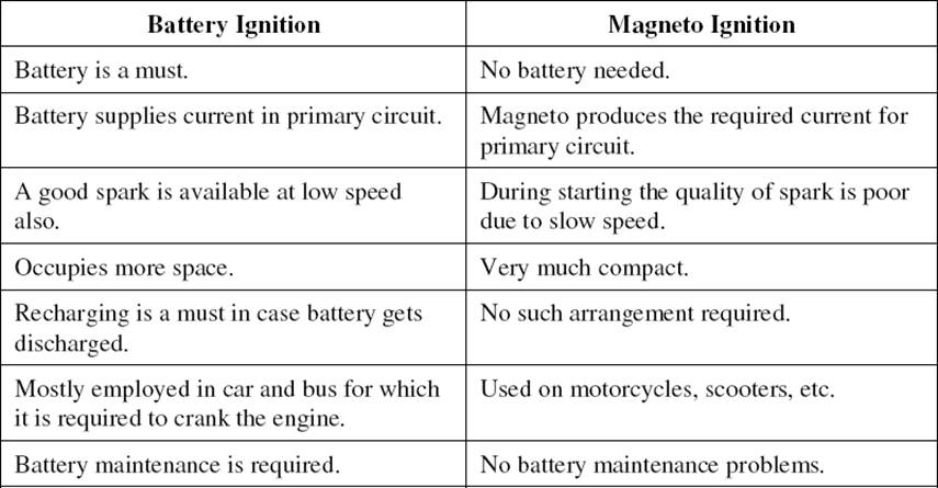
Ignition System: Basically Convectional Ignition systems are of 2 types : (a) Battery or Coil Ignition System, and (b) Magneto Ignition System. Both these conventional, ignition systems work on mutual electromagnetic induction principle. Battery ignition system was generally used in 4-wheelers, but now-a- days it is more commonly used in 2-wheelers also (i.e. Button start, 2-wheelers like Pulsar, Kinetic Honda; Honda-Activa, Scooty, Fiero, etc.). In this case 6 V or 12 V batteries will supply necessary current in the primary winding. Magneto ignition system is mainly used in 2-wheelers, kick start engines. (Example, Bajaj Scooters, Boxer, Victor, Splendor, Passion, etc.). In this case magneto will produce and supply current to the primary winding. So in magneto ignition system magneto replaces the battery.
Battery or Coil Ignition System
Figure shows line diagram of battery ignition system for a 4-cylinder petrol engine. It mainly consists of a 6 or 12 volt battery, ammeter, ignition switch, auto-transformer (step up transformer), contact breaker, capacitor, distributor rotor, distributor contact points, spark plugs, etc.
Note that the Figure 4.1 shows the ignition system for 4-cylinder petrol engine, here there are 4-spark plugs and contact breaker cam has 4-corners. (If it is for 6-cylinder engine it will have 6-spark plugs and contact breaker cam will be a hexagon).
The ignition system is divided into 2-circuits :
i. Primary Circuit : It consists of 6 or 12 V battery, ammeter, ignition switch, primary winding it has 200- 300 turns of 20 SWG (Sharps Wire Gauge) gauge wire, contact breaker, capacitor.

(ii) Secondary Circuit : It consists of secondary winding. Secondary Ignition Systems winding consists of about 21000 turns of 40 (S WG) gauge wire. Bottom end of which is connected to bottom end of primary and top end of secondary winding is connected to centre of distributor rotor. Distributor rotors rotate and make contacts with contact points and are connected to spark plugs which are fitted in cylinder heads (engine earth). (iii) Working : When the ignition switch is closed and engine in cranked, as soon as the contact breaker closes, a low voltage current will flow through the primary winding. It is also to be noted that the contact beaker cam opens and closes the circuit 4-times (for 4 cylinders) in one revolution. When the contact breaker opens the contact, the magnetic field begins to collapse. Because of this collapsing magnetic field, current will be induced in the secondary winding. And because of more turns (@ 21000 turns) of secondary, voltage goes unto 28000-30000 volts. This high voltage current is brought to centre of the distributor rotor. Distributor rotor rotates and supplies this high voltage current to proper stark plug depending upon the engine firing order. When the high voltage current jumps the spark plug gap, it produces the spark and the charge is ignited-combustion starts-products of combustion expand and produce power.
In this case magneto will produce and supply the required current to the primary winding. In this case as shown, we can have rotating magneto with fixed coil or rotating coil with fixed magneto for producing and supplying current to primary, remaining arrangement is same as that of a battery ignition system.

Lubrication System:
The splash system is no longer used in automotive engines. It is widely used in small four-cycle engines for lawn mowers, outboard marine operation, and so on.
In the splash lubricating system , oil is splashed up from the oil pan or oil trays in the lower part of the crankcase. The oil is thrown upward as droplets or fine mist and provides adequate lubrication to valve mechanisms, piston pins, cylinder walls, and piston rings. In the engine, dippers on the connecting-rod bearing caps enter the oil pan with each crankshaft revolution to produce the oil splash. A passage is drilled in each connecting rod from the dipper to the bearing to ensure lubrication. This system is too uncertain for automotive applications. One reason is that the level of oil in the crankcase will vary greatly the amount of lubrication received by the engine. A high level results in excess lubrication and oil consumption and a slightly low level results in inadequate lubrication and failure of the engine.
In a combination splash and force feed , oil is delivered to some parts by means of splashing and other parts through oil passages under pressure from the oil pump. The oil from the pump enters the oil galleries. From the oil galleries, it flows to the main bearings and camshaft bearings. The main bearings have oil- feed holes or grooves that feed oil into drilled passages in the crankshaft. The oil flows through these passages to the connecting rod bearings. From there, on some engines, it flows through holes drilled in the connecting rods to the piston-pin bearings. Cylinder walls are lubricated by splashing oil thrown off from the connecting-rod bearings. Some engines use small troughs under each connecting rod that are kept full by small nozzles which deliver oil under pressure from the oil pump. These oil nozzles deliver an increasingly heavy stream as speed increases. At very high speeds these oil streams are powerful enough to strike the dippers directly. This causes a much heavier splash so that adequate lubrication of the pistons and the connecting-rod bearings is provided at higher speeds.
If a combination system is used on an overhead valve engine, the upper valve train is lubricated by pressure from the pump.
A somewhat more complete pressurization of lubrication is achieved in the force-feed lubrication system . Oil is forced by the oil pump from the crankcase to the main bearings and the camshaft bearings. Unlike the combination system the connecting-rod bearings are also fed oil under pressure from the pump.
Oil passages are drilled in the crankshaft to lead oil to the connecting-rodbearings. The passages deliver oil from the main bearing journals to the rod bearing journals. In some engines, theseopening are holes that line up once for every crankshaft revolution. In other engines, there are annular grooves in the main bearings through which oil can feed constantly into the hole in the crankshaft. The pressurized oil that lubricates the connecting-rod bearings goes on to lubricate the pistons and walls by squirting out through strategically drilled holes. This lubrication system is used in virtually all engines that are equipped with semifloating piston pins.
In a full force-feed lubrication system , the main bearings, rod bearings, camshaft bearings, and the complete valve mechanism are lubricated by oil under pressure. In addition, the full force-feed lubrication system provides lubrication under pressure to the pistons and the piston pins. This is accomplished by holes drilled the length of the connecting rod, creating an oil passage from the connecting rod bearing to the piston pin bearing. This passage not only feeds the piston pin bearings but also provides lubrication for the pistons and cylinder walls. This system is used in virtually all engines that are equipped with full- floating piston pins.
Air Cooled System
Air cooled system is generally used in small engines say up to 15-20 Kw and in aero plane engines. In this system fins or extended surfaces are provided on the cylinder walls, cylinder head, etc. Heat generated due to combustion in the engine cylinder will be conducted to the fins and when the air flows over the fins, heat will be dissipated to air. The amount of heat dissipated to air depends upon : (a) Amount of air flowing through the fins. (b) Fin surface area. I Thermal conductivity of metal used for fins.
Advantages of Air Cooled System Following are the advantages of air cooled system : (a) Radiator/pump is absent hence the system is light. (b) In case of water cooling system there are leakages, but in this case there are no leakages. I Coolant and antifreeze solutions are not required. (d) This system can be used in cold climates, where if water is used it may freeze.
Disadvantages of Air Cooled System (a) Comparatively it is less efficient. (b) It is used only in aero planes and motorcycle engines where the engines are exposed to air directly. Water Cooling System: In
this method, cooling water jackets are provided around the cylinder, cylinder head, valve seats etc. The water when circulated through the jackets, it absorbs heat of combustion. This hot water will then be cooling in the radiator partially by a fan and partially by the flow developed by the forward motion of the vehicle. The cooled water is again recirculated through the water jackets.
Types of Water Cooling System There are two types of water cooling system : Thermo Siphon System In this system the circulation of water is due to difference in temperature (i.e. difference in densities) of water. So in this system pump is not required but water is circulated because of density difference only.

Pump Circulation System In this system circulation of water is obtained by a pump. This pump is driven by means of engine output shaft through V-belts.

Performance Calculation: Engine performance is an indication of the degree of success of the engine performs its assigned task, i.e. the conversion of the chemical energy contained in the fuel into the useful mechanical work. The performance of an engine is evaluated on the basis of the following : (a) Specific Fuel Consumption. (b) Brake Mean Effective Pressure. I Specific Power Output. (d) Specific Weight. (e) Exhaust Smoke and Other Emissions. The particular application of the engine decides the relative importance of these performance parameters.
For Example : For an aircraft engine specific weight is more important whereas for an industrial engine specific fuel consumption is more important. For the evaluation of an engine performance few more
parameters are chosen and the effect of various operating conditions, design concepts and modifications on these parameters are studied. The basic performance parameters are the following : (a) Power and Mechanical Efficiency. (b) Mean Effective Pressure and Torque. I Specific Output. (d) Volumetric Efficiency. (e) Fuel-air Ratio. (f) Specific Fuel Consumption. (g) Thermal Efficiency and Heat Balance. (h) Exhaust Smoke and Other Emissions. (i) Specific Weight.
Power and Mechanical Efficiency The main purpose of running an engine is to obtain mechanical power.
(or torque) as well as speed. The force or torque is measured with the help of a dynamometer and the speed by a tachometer. The power developed by an engine and measured at the output shaft is called the brake power (bp) and is given by bp=2Πnt/60 where, T is torque in N-m and N is the rotational speed in revolutions per minute. The total power developed by combustion of fuel in the combustion chamber is, however, more than the bp and is called indicated power (ip). Of the power developed by the engine, i.e. ip, some power is consumed in overcoming the friction between moving parts, some in the process of inducting the air and removing the products of combustion from the engine combustion chamber.
Indicated Power It is the power developed in the cylinder and thus, forms the basis of evaluation of combustion efficiency or the heat release in the cylinder. Where,
I.P= PmLANK/60
pm = Mean effective pressure, N/m2, L = Length of the stroke, m, A = Area of the piston, m2, N = Rotational speed of the engine, rpm (It is N/2 for four stroke engine), and k = Number of cylinders. Thus, we see that for a given engine the power output can be measured in terms of mean effective pressure.
The difference between the ip and bp is the indication of the power lost in the mechanical components of the engine (due to friction) and forms the basis of mechanical efficiency; which is defined as follows :
Mechanical efficiency=bp/ip
The difference between ip and bp is called friction power (fp). Fp = ip – bp
Mechanical efficiency= b.p/(bp+fp)
Mean effective pressure is defined as a hypothetical/average pressure which is assumed to be acting on the piston throughout the power stroke. Therefore,
Pm=60Xi.P/LANk
where, Pm = Mean effective pressure, N/m2, Ip = Indicated power, Watt, L = Length of the stroke, m, A = Area of the piston, m2, N = Rotational speed of the engine, rpm (It is N/2 for four stroke engine), and k = Number of cylinders.
If the mean effective pressure is based on bp it is called the brake mean effective pressure( Pm), and if based on ihp it is called indicated mean effective pressure (imep). Similarly, the friction mean effective pressure (fmep) can be defined as, fmep = imep – bmep
The torque is related to mean effective pressure by the relation B.P=2Πnt/60
I.P=PmLANk/60
2Πnt/60=[bmep.A.L.(Nk/60)] or, T=(bmep.A.L.k)/2π
Thus, the torque and the mean effective pressure are related by the engine size. A large engine produces more torque for the same mean effective pressure. For this reason, torque is not the measure of the ability of an engine to utilize its displacement for producing power from fuel. It is the mean effective pressure which gives an indication of engine displacement utilization for this conversion. Higher the mean effective pressure, higher will be the power developed by the engine for a given displacement. Again we see that the power of an engine is dependent on its size and speed. Therefore, it is not possible to compare engines on the basis of either power or torque. Mean effective pressure is the true indication of the relative performance of different engines.
Specific Output Specific output of an engine is defined as the brake power (output) per unit of piston displacement and is given by,
Specific output=B.P/A.L Constant = bmep × rpm • The specific output consists of two elements – the bmep (force) available to work and the speed with which it is working. • Therefore, for the same piston displacement and bmep an engine operating at higher speed will give more output. • It is clear that the output of an engine can be increased by increasing either speed or bmep. Increasing speed involves increase in the mechanical stress of various engine parts whereas increasing bmep requires better heat release and more load on engine cylinder.
Volumetric Efficiency Volumetric efficiency of an engine is an indication of the measure of the degree to which the engine fills its swept volume. It is defined as the ratio of the mass of air inducted into the engine cylinder during the suction stroke to the mass of the air corresponding to the swept volume of the engine at
atmospheric pressure and temperature. Alternatively, it can be defined as the ratio of the actual volume inhaled during suction stroke measured at intake conditions to the swept volume of the piston.

The amount of air taken inside the cylinder is dependent on the volumetric efficiency of an engine and hence puts a limit on the amount of fuel which can be efficiently burned and the power output. For supercharged engine the volumetric efficiency has no meaning as it comes out to be more than unity.
Fuel-Air Ratio (F/A) Fuel-air ratio (F/A) is the ratio of the mass of fuel to the mass of air in the fuel-air mixture. Air-fuel ratio (A/F) is reciprocal of fuel-air ratio. Fuel-air ratio of the mixture affects the combustion phenomenon in that it determines the flame
propagation velocity, the heat release in the combustion chamber, the maximum temperature and the completeness of combustion. Relative fuel-air ratio is defined as the ratio of the actual fuel-air ratio to that of the stoichiometric fuel-air ratio required to burn the fuel supplied. Stoichiometric fuel-air ratio is the ratio of fuel to air is one in which case fuel is completely burned due to minimum quantity of air supplied.
Relative fuel-air ratio, =(Actual Fuel- Air ratio)/(Stoichiometric fuel-Air ratio)
Brake Specific Fuel Consumption Specific fuel consumption is defined as the amount of fuel consumed for each unit of brake power developed per hour. It is a clear indication of the efficiency with which the engine develops power from fuel. B.S.F.C= Relative fuel-air ratio, =(Actual Fuel- Air ratio)/(Stoichiometric fuel-Air ratio) This parameter is widely used to compare the performance of different engines.
Thermal Efficiency and Heat Balance Thermal efficiency of an engine is defined as the ratio of the output to that of the chemical energy input in the form of fuel supply. It may be based on brake or indicated output. It is the true indication of the efficiency with which the chemical energy of fuel (input) is converted into mechanical work. Thermal efficiency also accounts for combustion efficiency, i.e., for the fact that whole of the chemical energy of the fuel is not converted into heat energy during combustion.
Brake thermal efficiency = B.P/mf* Cv
where, Cv = Calorific value of fuel, Kj/kg, and mf = Mass of fuel supplied, kg/sec. • The energy input to the engine goes out in various forms – a part is in the form of brake output, a part into exhaust, and the rest is taken by cooling water and the lubricating oil. • The break-up of the total energy input into these different parts is called the heat balance. • The main components in a heat balance are brake output, coolant losses, heat going to exhaust, radiation and other losses. • Preparation of heat balance sheet gives us an idea about the amount of energy wasted in various parts and allows us to think of methods to reduce the losses so incurred.
Exhaust Smoke and Other Emissions: Smoke and other exhaust emissions such as oxides of nitrogen, unburned hydrocarbons, etc. are nuisance for the public environment. With increasing emphasis on air pollution control all efforts are being made to keep them as minimum as it could be. Smoke is an indication of incomplete combustion. It limits the output of an engine if air pollution control is the consideration.
Emission Formation Mechanisms: (S.I) This section discusses the formation of HC, CO, Nox, CO2, and aldehydes and explains the effects of design parameters.
HC emissions are various compounds of hydrogen, carbon, and sometimes oxygen. They are burned or partially burned fuel and/or oil. HC emissions contribute to photochemical smog, ozone, and eye irritation. There are several formation mechanisms for HC, and it is convenient to think about ways HC can avoid combustion and ways HC can be removed; we will discuss each below. Of course, most of the HC input is fuel, and most of it is burned during “normal” combustion. However, some HC avoids oxidation during this process. The processes by which fuel compounds escape burning during normal S.I. combustion are:
1. Fuel vapor-air mixture is compressed into the combustion chamber crevice volumes. 2. Fuel compounds are absorbed into oil layers on the cylinder liner. 3. Fuel is absorbed by and/or contained within deposits on the piston head and piston crown. 4. Quench layers on the combustion chamber wall are left as the flame extinguishes close to the walls. 5. Fuel vapor-air mixture can be left unburned if the flame extinguishes before reaching the walls. 6. Liquid fuel within the cylinder may not evaporate and mix with sufficient air to burn prior to the end of combustion. 7. The mixture may leak through the exhaust valve seat.
present in significant quantities in gasoline-fueled engines, but they are an issue when alcohol fuels are used. Aldehydes are thought to cause lung problems. So far, little information of engine calibration effects on aldehyde formation is available.
Emission Formation In C.I. Engine For many years, diesel engines have had a reputation of giving poor performance and producing black smoke, an unpleasant odor, and considerable noise. However, it would find it difficult to distinguish today‟s modern diesel car from its gasoline counterpart. For diesel engines the emphasis is to reduce emissions of Nox and particulates, where these emissions are typically higher than those from equivalent port injected gasoline engines equipped with three-way catalysts. Catalyst of diesel exhaust remains a problem insofar as researchhas not yet been able to come up with an effective converter that eliminates both particulate matter (PM) and oxide of nitrogen (Nox).
Principle C.I. Engine Exhaust Constituents For many years, diesel engines have had a reputation of giving poor performance and producing black smoke, an unpleasant odor, and considerable noise. However, it would find it difficult to distinguish today‟s modern diesel car from its gasoline counterpart. Concerning CO and HC emissions, diesel engines have an inherent advantages, therefore the emphasis is to reduce emissions of Nox and particulates, where these emissions are typically higher than those from equivalent port injected gasoline engines equipped with three-way catalysts. Catalyst of diesel exhaust remains a problem insofar as research has not yet been able to come up with an effective converter that eliminates both particulate matter (PM) and oxide of nitrogen (Nox). In the same manner as with SI engines, the air/fuel ratio of the diesel engine has a significant impact on the level of pollutant concentrations but this parameter is not freely available for minimizing pollution.
Problems: To determine Brake power, Indicated Power, Frictional Power, Brake Thermal Efficiency, Indicated Thermal Efficiency, Mechanical Efficiency, Relative Efficiency, Volumetric Efficiency, Brake Specific Fuel Consumption, Indicated Specific Fuel Consumption, Indicated mean effective pressure, Brake mean effective pressure.
Problems: To determine Brake power, Indicated Power, Frictional Power, Brake Thermal Efficiency, Indicated Thermal Efficiency, Mechanical Efficiency, Relative Efficiency, Volumetric Efficiency, Brake Specific Fuel Consumption, Indicated Specific Fuel Consumption, Indicated mean effective pressure, Brake mean effective pressure.
2.A six cylinder, 4 stroke SI engine having a piston displacement of 700cm3 per cylinder developed 78Kw at 3200 rpm and consumed 27 kg of petrol per hour. The calorific value of the fuel is 44MJ/kg. Estimate
1.The volumetric efficiency of the engine if the air-fuel ratio is 12 and intake air is at 0.9bar,32oC. 2.Brake thermal efficiency and brake torque. For air R=0.287 Kj/kgK.
Source: http://fmcet.in/MECH/ME6404_uw.pdf
Web site to visit: http://fmcet.in
Author of the text: indicated on the source document of the above text
If you are the author of the text above and you not agree to share your knowledge for teaching, research, scholarship (for fair use as indicated in the United States copyrigh low) please send us an e-mail and we will remove your text quickly. Fair use is a limitation and exception to the exclusive right granted by copyright law to the author of a creative work. In United States copyright law, fair use is a doctrine that permits limited use of copyrighted material without acquiring permission from the rights holders. Examples of fair use include commentary, search engines, criticism, news reporting, research, teaching, library archiving and scholarship. It provides for the legal, unlicensed citation or incorporation of copyrighted material in another author's work under a four-factor balancing test. (source: http://en.wikipedia.org/wiki/Fair_use)
The information of medicine and health contained in the site are of a general nature and purpose which is purely informative and for this reason may not replace in any case, the council of a doctor or a qualified entity legally to the profession.
The texts are the property of their respective authors and we thank them for giving us the opportunity to share for free to students, teachers and users of the Web their texts will used only for illustrative educational and scientific purposes only.
All the information in our site are given for nonprofit educational purposes