Fastening Mechanisms used by Motor Vehicle Manufacturers.
Solid Rivets
The strength of a riveted joint depends on several factors; the material in which the rivets and plates to be riveted are made, whether the holes for the rivets are punched or drilled and the workmanship involved in the riveting of the joint. In light sheet metal, rivets are usually applied in the cold state so that there is virtually no possibility of distortion. However, in heavier metal plate riveted joints often have to be comparable with surrounding metal and so the rivets are inserted in the hot state as this increases the strength of the joint.
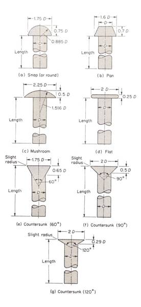 Rivets used in hot riveting are made from steel and/or iron, while for cold working rivets made from copper, brass, aluminium and aluminium alloys are used. In body work, steel rivets are used on commercial chassis frames and also on fabricated sections such as sub-frames and structural load bearing members. In addition aluminium rivets (NR5 and NR6) are used on alloy frame construction in the body building industry.
Rivets are classified according to the shapes of their heads, diameter and length of the rivet .The shape of the rivet head is selected according to the intended use of the work piece to be riveted.
Figure 1: Small Rivet Heads
Most important, the length of the rivet must correspond to the total thickness of the components to be joined. The various types of rivets are shown in figure 1, together with their British Standard proportions.
The snap or round head rivet is used where high strength is required; the pan head; similar to the snap head, is also used where strength is required; the mushroom is used in thin sheet metal which would be weakened by the use of counter sunk rivets; flat head rivets are used for riveting flat bar and angle sections to thin metal sheet as the head is fairly flush and does not obstruct; and the counter sunk head rivet is used when the surface of the component must remain smooth.
Rivet Holes
Rivet holes can be punched or drilled. Punched holes are generally slightly conical and for an efficient joint the work has to be arranged so that the holes are brought together with their smaller ends adjacent. Punched holes also have ragged edges which must be smoothed otherwise they will decrease the shearing resistance of the rivets.
Drilling produces holes with smooth edges, and has the further advantage that it can be carried out with plates in position so that there is no damage due to badly aligned holes. A joint formed with drilled holes is about 8 per cent stronger than a joint made with punched holes.
Riveting Dimensions
The diameter of a rivet is usually determined by D=1.2√ t, where D is the diameter of the rivet and t is the thickness of the plate.
The allowance for riveting is the allowance for the head of the rivet and is the amount of rivet showing above the plate before riveting.
Snap head = 1.5D Counter sunk head = 0.15D
Flat head =0.5D
The pitch of a rivet is the spacing between the rivet centres and can be calculated from the principle that the part of the plate in between each pair of holes should be the same strength as one rivet, and therefore if the pitch is less than 3D the plate between the rivets will be too weak. The pitch can then be extended to 8D in special cases, but above that the plate will tend to buckle.
The width of lap is the distance from the centre of the rivet to the edge of plate, and is generally taken as 1½D so that a single riveted lap joint would have an overlap of 3D and a double lap joint, an overlap of 5D.
Types of Riveted Joints
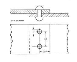 The smallest form of riveted joint is the ‘single lap joint’ (figure 2) in which the plates overlap a short distance with a single row of rivets along the centre of the lap. The ‘double riveted lap joint’ has two rows of rivets arranged either in line or staggered alternately. The ‘single strap butt joint’ consists of two plates butted edge to edge with a strap covering the centre of the butt and riveted down each side (figure 3). The ‘double strap butt joint’ is the same as the single strap butt joint with the addition of a second strap on the opposite side.
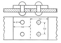
Figure 2: Single Riveted Lap Joint
Figure 3: Butt Joint
1.1 Methods of Joining
A single riveted joint has an efficiency of only about 55 per cent. In a double riveted joint this is raised to about 70 per cent, whilst in a treble riveted joint 80 per cent or greater efficiency may be attained.
1.2 Riveting Procedure
Plates to be riveted should be clamped together with their rivet holes in alignment. If hot rivets are being used, they should be at forging temperature and the operation should be completed before they become ‘black hot’.
For snap head rivets, a punch or tool (snap) having a half-spherical cavity similar to the rivet head is used to support the rivet head, while the other end punch to the rivet is riveted over by holding a similar punch to the rivet end and striking it with a hammer, thus forming a second cup head on the other end of the rivet.
The aim in riveting is to swell the body of the rivet until it completely fills the holes and to complete the process as quickly as possible while the rivet is still very hot so that there is maximum contraction of the rivets after riveting to pull the plates together. Pneumatic or air operated hammers are used extensively for closing over rivet heads. They are designed to deliver the right weight of blow at the correct speed to form the rivet head speedily and accurately. For cold riveting the closure of the rivet similar to that of a hot rivet except that the metal is not as plastic and greater difficulty will be encountered in swelling the rivet shank to fill the hole. Cold riveted plates cannot be as tight as with hot rivets to pull them together. Care should be taken that the rivet head is spread evenly in all directions and not bent over in one direction only. This is often helped by giving the rivet a few preliminary blows with the ball end of a hammer, thus spreading the rivet a little before using the riveting tool. Counter sunk rivets should be supported with a flat headed punch.
 The initial spreading is done with the ball end of a hammer and the head is finished with the flat end of a hammer. When joints are large it is advisable not to start at one end of the work piece but to rivet the extremities first and next the centre, then the rest of the joint. This eliminates creeping of the plates and misalignment of the holes (figure 4).
Figure 4: Riveting Procedure
Bifurcated, Tubular and Semi-Tubular Rivets
These rivets have the outstanding advantage that there is no swelling of the solid portion of the shank during the closure operation. They are used extensively for the joining of soft materials such as clutch linings to metal. Only a small percentage is used in the body building industry.
1.3 Blind (Pop) Rivets
The blind rivet was originally developed in the 1930s for use in the aircraft industry but the last decade has seen its adoption in the light engineering industries. It is now employed as a standard sheet metal fastener in cars, buses and all forms of commercial vehicles. Blind rivets, as their name implies, are rivets which can be set when access is limited to only one side of a structure. They are invaluable both in car construction work where many of the panel assemblies are of the double skinned type so that accessibility would be impossible for conventional riveting methods, and also in body repair work as they eliminate any unnecessary stripping of interiors. Blind rivets are generally known as ‘pop rivets’, which is the original trade name of the firm who pioneered and manufactured them, namely the George Tucker Eyelet Co. Ltd. The pop rivet comprises a hollow rivet assembled to a headed steel mandrel or stem (figure 5). It is inserted into a predrilled hole of the correct size in the work piece and a special tool containing a gripping device is applied to the mandrel or stem of the rivet.
When the tool is operated, either manually or automatically, the mandrel head is drawn into the hollow rivet, expanding the end of the rivet which is on the blind side of the structure and at the same time pulling the material together. When and only when, a tight joint has been formed, the mandrel breaks at a predetermined position, so that the mandrel head is left as a plug in the bore of the rivet (figure 6 (a)). The spent portion of the mandrel is then ejected from the tool. Pop rivets are manufactured from aluminium alloys BSL58, Monel DTD10B, mild steel EN2 and copper. They are supplied with domed or counter sunk (120º or 100º) heads in diameters of 2.4mm, 3.2mm, 4.0mm, 4.8mm, 5.6mm, and 6.4mm for riveting thickness up to 12.7mm. Shear strengths range from 110lb for 2.4mm. Diameter aluminium alloy rivets, to 1600lb for 6.4mm diameter Monel rivets. Owing to the high clenching action of the rivet, tensile strengths are in excess of these figures.
 Figure 5: ‘Pop’ Rivet
(a) ‘Pop’ riveting sequence (B) Standard open–type rivet
There are four types of pop rivets:
Another company who specialize in making blind rivets is Avdel and they offer a system of riveting which is widely used on vehicle body construction, especially commercial vehicles. There are two types of riveting systems.
The Chobert riveting system operates on an entirely different principle from all other blind riveting systems (figure 9). Instead of a ‘break stem’ type of mandrel, there is a mandrel with a tapered hardened steel head larger in diameter than the tapered bore of the rivet.
The mandrel is drawn through the rivet towards the head and is thus part of the placing tool rather than the component. It is possible to extend the mandrel length to accommodate a charge of up to 100 rivets and to achieve a rate of placing up to 2000 per hour. The Chobert rivet is made in a wide range of materials and sizes. Head forms currently available include snap, mushroom, flat, counter sunk and sizes range from 2.38mm to 6.35mm diameter.
Materials include a wide range of aluminium alloys, cadmium plated steel and brass. They are supplied in tube loaded form each 12.5in (317.5 mm) long and containing up to 100 carefully aligned rivets. The tubes can be used in special tools which can be either manually or pneumatically operated. If additional strength or water tightness is required the rivets can be pinned, giving in effect a solid rivet.
The Chobert grovit system has been developed so that the widest range of materials (such as wood, plastic and aluminium) may be joined. The grovit has grooves on its shank which bite firmly into the material when the rivet is expanded (figure 10). The rivets can also be used in the high speed Chobert system. These types of riveting systems are ideal for mass production and are invaluable in the body building industry where speed and economy is essential (figure 11).

Figure 10: The Chobert Grooved Rivet
Blind Riveting Tools
The majority of blind riveting tools have been designed on the assumption that the operator will be moving around a stationary structure, as in body building. However some stand tools are available. The range of tools has been designed to cater for all riveting conditions, whether they are used on high speed assembly production lines or for occasional use.
The basic types of tools consist of:
In addition various heads are available for attaching to either manual or power operated tools which can gain access to restricted places. In order to change the rivet diameter or type of rivet being used, it is necessary merely to change the nose-piece or the gripping jaws which hold the mandrels. It must be remembered that certain special rivets and fasteners can only be used by their appropriate setting tool.
1.4 Methods of Joining
Rivet Selection
The following factors must be considered when selecting the type of rivet to be use on a particular job.
Rivet diameter
In some cases this may be decided by the size of an existing hole. When designing new work the main factor is usually the shear or tensile strength required from the riveted joint. In load bearing joints the diameter of the rivet should be at least equal to the thickness of the thickest sheet but should not be greater than three times the thickness of the sheet.
Hole size
Drill sizes for each diameter of rivet are usually specified by the manufacturers. These are usually designed to give clearance of 0.002in. (0.05mm) to 0.005in. (0.13mm) between the rivet and the hole and in the case of rivets capable of only limited radial expansion these recommendations must be followed if maximum efficiency is to be achieved.
Rivet length
Manufacturers also specify the correct rivet length to be used on a given thickness of material. It is often an advantage to use rivets which are longer than those recommended as they will set satisfactorily on thinner materials and the longer length, when expanded, increases the grip of the rivet but the higher cost for longer rivets should be taken into account before doing so.
Pitch of rivets
In load bearing joints the distance between rivets in the same row should not exceed six times the rivet diameter. Even when the joint is non load bearing the rivet pitch should not exceed twenty four times the thickness of the thinnest sheet in the joint.
Edge distance
In lap or butt joints which are likely to be subjected to shear or tensile loads, rivet holes should not be drilled within a distance equal to two rivet diameters from the edge of the sheet but should not exceed twenty four rivet diameters.
Rivet material
The choice of rivet material will normally be related to the strength required from the riveted joint. Usual rivet materials are steel, aluminium alloy, copper and monel. Other factors affecting the choice are weight, high temperatures and corrosion which can occur when different metals are joined together.
Mandrel type
The break stem mandrel is usually chosen where the rivet is to act as a waterproof plug and also where it would be inconvenient to eject the mandrel head on the blind side of the enclosed structure. The break head mandrel is used where weight is a factor and where a comparatively clear hole is required through the rivet set.
1.5 Blind Fasteners
The Avdelok System
This is not a blind fastener but has a number of advantages over the conventional rivet or nut and bolt which it replaces. The Avdelok is a two piece high strength fastener consisting of a bolt made from NR6 material and a collar made of N5 material (figure 12). It gives a high clench action and a positively locked nut or collar which is proof against vibrations. It can be placed very simply by manual or pneumatic tools. The Avdelok bolt is placed through the prepared hole and the collar is slipped onto the other side of the joint (figure 12). The nose of the tool is then pushed over the tail of the bolt and the trigger is pulled. This draws the bolt tight, clamping the sheets together. The pull continues until the nose of the tool is drawn over the collar, compressing the collar until it is swaged into the grooves of the pin. The tail of the bolt breaks off at the deep breaker groove, flush with the collar. No finishing is needed. This system is employed in such applications as chassis cross bearer brackets on commercial bodies.
The Avlok System
This is similar to the Avdelok System in so much as it is a bolt and deformable nut, but differs in that it is a blind fastener capable of being placed from one side of the work only (figure 14). Its high positive clamp-up ensures great strength and good fatigue resisting properties. It can be used with manual or pneumatic tools. The Avlok is inserted into a predrilled hole with the tool placed over the tail of the bolt and the bolt is drawn tightly into the nut clamping the plates. At a predetermined load the bolt shears, leaving a portion of the bolt firmly locked in position inside the sleeve. The tail of the bolt is then ejected from the tool (figure15).
The Nutsert System
This is a steel threaded insert of high strength (figure 16) which can be placed by any of three specially designed tools. It is placed on the threaded drive screw of the placing tool and inserted into a prepared hole in the work piece. The drive screw turns clockwise, drawing the tapered nose portion of the Nutsert back into its outer shell and thus causing the shell to expand into the preformed hole. The drive screw is then withdrawn, leaving the Nutsert permanently and tightly placed in the hole and ready to receive either a screw or bolt. It can be used on all types of metals and also plastic and timber and is made in a wide range of thread sizes both British and metric (figure 17).
The Jo-bolt System
The Jo-bolt consists of a high tensile steel nut and bolt and a stainless steel deformable sleeve. It is a blind high strength clamp fixing made in sizes from 3.97mm to 4.76mm diameter and is available with counter sunk and hexagon head forms. The Jo-bolt is inserted into a predrilled hole and the placing tool is located onto the head of the nut, holding it static, while the inner adaptor rotates the bolt. This draws the sleeve up over the tapered end of the nut so that the work pieces are clamped together and at a predetermined load the bolt shears off flush with the head (figure18).
1.6 Joining by Screws and Bolts
Wood Screws
Joining by wood screws is an essential part of the construction of vehicle bodies which incorporate timber. Screws are available in steel, brass and bronze with a variety of alternative finishes. Sizes range from no.2 (1.6mm) to no.8 (7.9mm) and lengths vary from (6.35mm) up to 4 inches (101.6mm) and longer in special cases. The head types include the standard countersunk (used in most timber fixings), round head (sometimes used when fixing metal fittings to wood) and raised head (used when fixing mouldings where the raised head gives a decorative effect). A popular type of screw head, the Philips needs a special screwdriver with a cross pointed tip. In body shops wood screws are applied by hand or with special power operated screwdrivers which are either electrically or pneumatically operated.
Metal Screws (Self-tapping Screws)
Often there is a need for a fastening which will fix two or more parts together securely for indefinite periods, yet can be dismantled if necessary. Since World War II, the self-tapping screw has in many cases taken the place of more traditional fastenings and has justified itself completely on all types of motor vehicles. It is a very hard steel screw designed for joining metal to metal and is used for joining metal pressings and exterior fittings. The screw is inserted into a predrilled hole and it cuts its own thread in the metal, thus making a very secure joint. Screws are available in stainless steel and in steel with various finishes and gauges range from no.4 to no.14 and lengths from ¼ (6.35mm) to 2.5 inches (63.5mm). The types of heads available are countersunk, round head, raised countersunk, pan-head, mushroom head and hexagon head. Most heads have a single slot for insertion of a screwdriver; some known as Posidriv heads (figure19) have a star type slot and must be placed with a special type of screwdriver.
Figure 19: Pozidriv Self-Tapping Screw
Self-tapping screws are partially useful to the body engineer and trimmer since no access is needed to the rear side of the work, it being necessary simply to drill the requisite size of the hole and drive the screw home. The screw will stay secure until removal is necessary and can be removed and replaced many times without becoming slack if reasonable care is taken. Typical applications are mounting of door pillar trim pads, carpeting or rubber matting, parcel shelves, glove boxes, window cappings, ashtrays and kick plates.
Figure 20: Spat System Screw
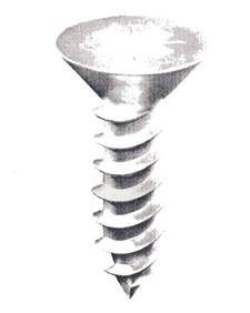 G.K.N. Screws and Fasteners Ltd. have devised a system for self-tapping screws called the spat system (figure 20) which eliminates the necessity for the predrilled or punched hole required in normal self-tapping methods. This system uses a special self-piercing and tapping screw which is placed by using a pneumatically operated gun with a driver head to fit the Posidriv style screw. First a high energy impact is provided to pierce the sheet metal with the point of the screw and then a rotary action drives the screw home. This gives a holding power at least 30 per cent better than the standard self-tapping screws. Spat system screws are available in the usual plated finishes with countersunk, pan, raised countersunk and flanged heads; all have the Posidriv recess. Screw sizes are from no.4 to no.10 and lengths from 7.938mm to 57.1mm. The spat gun system has been designed to provide sufficient impact for the screws to pierce a maximum sheet metal thickness of 18 S.W.G. 0.048 inches or 1.2mm.
Steel Hammer Drive Screws
These sheet metal fasteners (figure 21) are used only where permanent fixing is required as they are difficult to extract once placed. They are made in a very hard steel and the head shapes available are round head and countersunk. The screws are inserted in predetermined holes of the correct size and hammered so that the spiral thread is forced to cut into the material. The cutting action of the thread reduces the size of the hole after the pilot point has passed through.
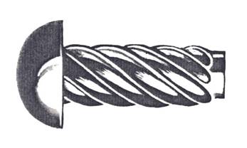
Figure 21 : Hammer Driven Screw
Screw Nails
These are made of hardened steel and are used for fastening thin sheet metal onto wood structures (figure 22). They are hammer driven through light gauge sheet metal taking care not to bend or break them, so that the hardened spiral thread cuts into the burr in the sheet metal and then worms its way into the wood. This makes a secure metal to wood joint which is ideal for paneling in the construction of vehicle bodies. The screws are obtainable with countersunk, flat and round heads.

Figure 22 : Screw Nail
Coach Screws
These are designed for securing heavy gauge metal and fittings to timber and are obtainable with either hexagon or square heads suitable for using a spanner or socket wrench. Sizes range from 4.763mm diameter up to 12.7mm and in lengths from 19mm to 254mm.
Bolting
Bolts are used extensively in the manufacture of motor vehicles, so components which are built in sections and then bolted together can easily be dismantled for repair or replacement. One example of this type of construction is the car body, which has certain panels which are made separately and later bolted in position so that they can be replaced as individual units if damaged. Another application of bolting is in cases where fabrications are too large for workshop assembly; then the article is made in sections which are assembled on site.
A bolt is a cylindrical rod having a head on one end and a thread cut along part of its length from the other end. Bolts are available in mild steel, alloy steel, stainless steel and brass and can be made of other metals and alloys for special applications. A nut and bolt is the most common means of joining. The unthreaded portion of the shank of the bolt is intended for fitting into clearance holes and a water washer can be used to minimize the effect of friction between the head of the bolt and the parent metal. A spring washer placed under an ordinary nut assists in preventing the slackening of the nut when the joint is subject to vibrations. The following types of heads are available on bolts:
1. Hexagon Head: This is the most frequently used shape and is suitable for all spanners.
2. Square Head: The square headed bolt is used mainly for heavy engineering and structural work.
3. Countersunk Head: A bolt of this type has a head shaped to fit into conical recesses in the work surface so that it lies level and flush. A slot is provided in the head for insertion of a screwdriver.
Set Screws (Machine Screws)
 A set screw is similar to a bolt but has the whole of its cylindrical shank threaded (figure 23). Set screws are used either to fix two pieces of metal together or to adjust the distance of one piece relative to the other. They are placed by passing each through a clearance hole in the top piece of metal and screwing it into a hole tapped out with a thread in the lower piece of metal. Countersunk, round, cheese and pan heads are available with either slotted or star recesses.
Figure 23 : Set Screw
1.7 Nuts
A nut is a shaped block of metal internally cut to form a thread. It is usually made from mild steel although other metals and alloys can be used for special purposes. Common nuts are:
1. Hexagonal plain nut: used in all classes of engineering.
2. Square nut: used in heavy engineering and structural work and also in coach building.
3. Castellated nut and slotted nut: used where the nut must always remain tight and slotted to take split-pins which act as a locking device.
4. Lock nuts: these are thinner than the normal nut and are fitted beneath the main nut to act as a locking device.
Clinch Nuts or Hank Rivet Bushes
This is a captive nut (figure 24) used for blind hole fixing in thin sheet metal. It is so called because a threaded nut is held securely in position by an annular rivet, the head of which is hammered flat around the hole to form a secure anchorage (figure 25).
 Figure 24 : Clinch Nut or Hank Rivet Bush
Figure 25 : Hank Rivet Bush Fixing Procedure
Aerotight Nut
This nut is designed for use in conditions of severe vibration. On the top of the nut there are two threaded cantilever arms which are deflected downwards and inwards. When the bolt is passed through the nut these arms are forced out towards their original position thus causing them to grip the thread very tightly.
Nyloc and Clevelock Nuts
These are self-locking nuts each with a built in moulded nylon insert made of smaller diameter than the nuts normal thread (figure 26). When the nut is screwed onto the bolt it runs freely until the end of the bolt meets the nylon insert. Further tightening of the bolt forces a thread onto the nylon insert making the nut grip the bolt more tightly thus creating a shock and vibration proof nut.
1.8 Fastening Devices
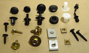 Spring steel fasteners directly contribute to an ever increasing degree of automation and have probably saved the motor industry millions of pounds during the last decade by enabling massive economies of labour and time in assembly. Industry data points to the fact that over 50 per cent of the total cost of a motor is in the area of assembly. A large portion of this arises from the time and labour expended in picking up and putting together a number of parts, some of them relatively small and this is where spring steel fasteners achieve marked savings compared with prewar methods. Another ancillary industry affected by the advent of spring fasteners is the repair industry; here economies are less dramatic but spring fasteners still make valuable savings in time, labour and handling. All of these types of clips are made from specially treated spring steel which retains its original spring locking power so that the clips are re-usable and hence economical. Other advantages of these clips are that they are easy to apply, they eliminate the use of washers and nuts, glass, plastic and other materials can be fastened together without fear of damage. One of the firms who manufacture these clips is Firth Cleveland Fastenings Ltd., who have developed the ‘spire speed nut’ which is used considerably in the car industry.
Spire Speed Nut
This nut has a double locking action which operates by means of an arched base and arched prongs. Since the introduction of this nut, hundreds of different fastenings have been introduced over the years and in some private cars over 200 spring steel fastenings are used.
Spire Flat Nut
The flat nut (figure 27) has replaced the threaded nut plus lock or plain washer. It is available in a wide variety of sizes to suit machine screws and sheet metal self tapping screws. First a hole is drilled in the appropriate panels then the self-tapping screw is placed through the panels and pushed into the spire nut or clip, making sure that the prongs point outwards. When the nut is tightened it is locked both by the self-energizing spring lock of the base and by the compensating thread lock as the arched prongs engage the thread. These free acting prongs compensate for tolerance variations and the combined forces of the thread and spring locks are claimed to eliminate any risk of loosening by vibration.
Captive Nut – ‘U’ Type
This nut (figure 28) is widely used for fastening blind assemblies in the motor industry. It can be assembled to the panels by hand by a skilled operator – no welding or riveting is required. The nut allows a certain degree of ‘float’ which facilitates speedy assembly. It remains captive to the panel, anchored by means of a sheared tongue on the lower leg which drops into the mounting hole and holds the nut in the screw receiving position. The range available covers many panel thicknesses and screw sizes. As the nut is pushed onto the panels edge then over a predrilled hole a locking tongue seats into the hole thus holding the nut in position. The second panel is aligned and the screw driven through this panel into the captive nut which holds it in place. This type of fastener has the advantage that it can be painted because there is no danger of clogging during any spraying operation.
Captive Nut – J Type:
This is similar in concept to the ‘U’ type nut bolt but with a shorter leg designed to snap into a clearance hole (figure 29). The ‘J’ type nut is easily started over the edge of a panel and pressed into position with the thumb. A typical application for ‘J’ nuts in the motor industry is the replacement of reinforcing rings and blind bushed on headlamp assemblies: The short leg on the front side of the nut is clipped into screw receiving positions on the wing aperture and ensures a good seal between gasket and wing thus precluding mud leakage.
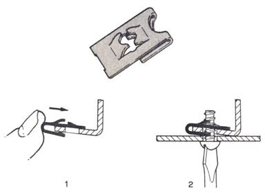
Figure 29: ‘J’ Type Captive Nut
Nut Grip
The nut grip (figure 30) is used in a square hole and replaces costly welded cage nuts and similar fastenings. It is installed into the panel by hand where it remains captive. The fully threaded nut in the cage is permitted to float slightly to overcome the problem of misaligned holes and is fitted after the finishing process at any convenient point on the production line. Three sizes of cage, covering threads from 6 BA up to 9.525mm BSF/BSW or Unified threads are available.
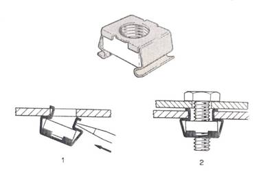
Figure 30 : Grip nut
Cable Clip
This is a special clip used for carrying cables and is fixed into predrilled holes thus eliminating the need for screw fixings (figure 31).
Figure 31  : Cable clip used for latching.
Sectional view shows clip in position in a panel.
Push On Clips
In addition to spring steel fasteners that are associated with threaded members there is a wide variety of push on clips. However these clips unlike the nuts are not pitched to follow the helix of a thread and the two sheared arms are of equal height. As the push on clip is forced over a plain stud fixing legs bite into the surface and on finally depressing the arched base which of course reacts as soon as the pressure is released the fixing legs are given a strong upward and inward pressure which firmly holds the fastener in position.

Figure 32 : Push-on Clips
(a): Simple push on clip showing clip in position.
(b): Tubular clip showing fitting sequence.
1. Clip is compressed as it enters hole in panel. Cut outs register with the panel allowing clip to expand and to be held firmly in position.
2. Second part of assembly is lined up and rivet and integral stub inserted.
3. Rivet is pressed home engaging turned in end if clip which expands to bite on rivet.
This has the effect of drawing the assembly together and removing any possibility of rattle. When using the push on clip it is important to ensure that the tolerance on the stud diameter is held to within reasonable limits; to get the best results from this type of fastener a tolerance of +0.002in. to 0.003 in. (0.05mm to 0.08mm) is recommended. Nowadays push on clips take many forms from the simple sheared type which is still widely used to the more modern blanked types the multi pronged clips for rectangular studs and now the plastic capped type. To fix this type of fastener it is of course necessary to have access to the back of the panel but if assembly is possible from one side only a tubular type can be used which consists of a small spring steel split tube. This is pushed into a hole in the panel where it remains captive and ready to receive the studs of the name badge or nameplate. Such tubular clips permit the assembly of a badge to the grille as a final operation. A removable version of this clip is also made for applications which have to be taken apart from time to time.
Non Metal Clips
The comparatively recent use of plastics has given rise to the development of new types of fastenings. The common fault with the strip or wire clip is that they become rusty and break either on removal or replacement and plastics have the advantage of being rust proof.
Tough rubber has great possibilities for certain types of fastenings. Some time ago a tough rubber strap was offered as an alternative to the traditional metal clip for retaining loose cables and wires It is still widely used in this way and rubber with a synthetic content is sometimes used for door check straps this demonstrates the strength of the material which clearly lends itself to many applications as yet unexploited.
1.9 Jointing By the Use of Adhesives in the Motor Trade
A bond between two surfaces may be regarded as a chain of three links the strength of the bond being that of the weakest link. The central link is the adhesive film between surfaces and the outer links are formed where the adhesive film meets the bonded surface. To form a strong surface linkage the adhesive must thoroughly wet the surface with liquid and when dry must adhere by penetration into the pores or fibres. In the case of smooth non porous surfaces such as glass or metal, a strong film of adhesive is best formed between the surfaces if these are joined at the appropriate stage in the drying of the applied adhesive. Many variations on this simple theme are possible and practicable but the character of the bond in a particular case will always be governed by how closely the technique used approximates to this ideal.
There are three basic groups of adhesives used in the motor trade:
1.10 Plastic captive nuts and trim panel fasteners
Plastic captive nuts are available in a large range of shapes and sizes for vehicle applications. They can be used in high corrosion areas and are designed to snap into a suitably punched hole in a metal panel where they will remain captive until final assembly. The shallow head gives highly desirable minimum clearance between panels. The combination of design and material permits the recommended screw to form its own thread by displacement resulting in high torque load and good anti vibration characteristics.
Plastic Capture Nut
Screws may be removed and the nuts reused providing the screws are the same size and thread form. This makes them ideal for applications such as inspection covers and service access. They are manufactured from glass filled nylon 66 which permits higher torque loadings. All other parts are manufactured from polypropylene (see figure 33).
Push in panel fasteners (W-buttons)
Push in panel fasteners are designed to hold board, plastic, rubber or other soft materials to secondary panels. No special tools are required as they assemble on the principle of a push in rivet. Simply push the W-button through the aligned panel holes so that it contracts on entry and then relaxes as it snaps through the total panel thickness securing the panels under tension. Many applications exist for W-buttons where a positive, attractive, light weight non corrosive fastening solution is required to assemble painted or PVC covered trim boards to fasten instruction badges or to blank off holes. In addition a special feature which makes the buttons particularly suitable for the automotive industry is the various styles of textured and colour moulded head to match adjacent panels (figure 34).

Figure 34 : Plastic Push-in Panel Fasteners
(a) W button (b) Christmas tree button
Christmas-tree buttons
Christmas tree buttons are a variation of push in fasteners and when they are pushed into the hole they take up great variations in panel thickness. These parts have a good tolerance of poor quality hole conditions. Although it is possible to remove the buttons they 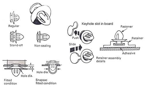 are not normally reusable.
Figure 35: Trim panel Fasteners
Trim panel fasteners
Are used principally in the automotive industry to attach door and tailgate panels to inner door panels. They are blind fixes ensuring a neat attractive assembly appearance. They allow panel removal for repair, service or inspection purposes. Easily fitted without the use of special tools they are positioned in a keyhole slot in the trim panel then firmly pushed home into the inner door panel mounting hole. Various types and sizes are available to suit different conditions and most have a flexible skirt which seals the mounting hole against entry of dirt or water (figure 35). Retainers where for a technical or styling reason, a keyhole slot is not feasible assembly can be simply achieved by using a separate retainer. With its own integral keyhole slot feature it can be attached to the trim panel either with a suitable adhesive or by heat staking. This will provide a secure attractive attachment with no evidence of fastener location.
Snapsacs
Provide increased retention and sealing for trim panel fasteners and their smooth surface eases assembly and removal.
Quick-release fasteners (quarter turn)
Consist of a stud cam and an optional retainer washer. A selection of lengths and head forms is available to suit a variety of assembly conditions. The washer allows the stud to be positively and securely located prior to and away from the final assembly point. Where the assembly is subject to routine servicing, the stud washer and cam stay securely mounted avoiding any risk of component loss (figure 36).
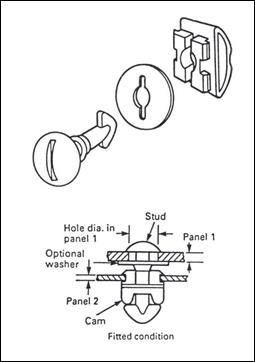
Figure 36 : Quick Release Fasteners (Quarter Turn)
Edge fasteners of the D type
Are lightweight fasteners which are ideal for assembling leather-cloth, soft plastics and fabrics to metal, rigid plastic or fibreboard panels. Fitted without the use of special tools they are pushed or tapped on to a convenient panel edge using a light hammer. The barbs retain the assembly securely in position on one side and the flat D side provides a neat flush appearance on the other. The friction grip version offers good retention without paint damage where corrosion resistance is paramount. They are manufactured from austempered carbon steel and normally supplied in phosphate and black finish (figure 37).
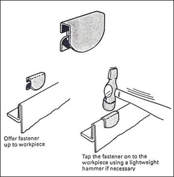
Figure 37 : Edge Fasteners, D Type

2.0 Specialised Tooling for Disassembling of Fastenings
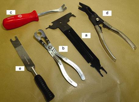
a. Body Trim Tool
This is a universal spring steel tool for removing body trims and clips and also weather strips, door trims, headlamp fittings, windscreen clips plastic mouldings, motifs and badges.
b. Door Handle Spring Clip Removers
These are specially designed pliers for fitting or removing the spring clips used on many modern door handles. One jaw sets in the neck of the spring whilst the other grips the other end and whole spring is then levered out.
c. Trim Panel Remover
This tool is designed to remove vehicle trim panels, upholstery and roof liners without damage. It also fits a wide variety of button-type fasteners used on vehicle trim.
d. Trim Clip Removers and Unhooking Pliers
e. Window Handle Clip Remover
Source: http://local.ecollege.ie/Content/APPRENTICE/liu/vbr_notes/module4/m4u1.doc
Web site to visit: http://local.ecollege.ie/
Author of the text: indicated on the source document of the above text
If you are the author of the text above and you not agree to share your knowledge for teaching, research, scholarship (for fair use as indicated in the United States copyrigh low) please send us an e-mail and we will remove your text quickly. Fair use is a limitation and exception to the exclusive right granted by copyright law to the author of a creative work. In United States copyright law, fair use is a doctrine that permits limited use of copyrighted material without acquiring permission from the rights holders. Examples of fair use include commentary, search engines, criticism, news reporting, research, teaching, library archiving and scholarship. It provides for the legal, unlicensed citation or incorporation of copyrighted material in another author's work under a four-factor balancing test. (source: http://en.wikipedia.org/wiki/Fair_use)
The information of medicine and health contained in the site are of a general nature and purpose which is purely informative and for this reason may not replace in any case, the council of a doctor or a qualified entity legally to the profession.
The texts are the property of their respective authors and we thank them for giving us the opportunity to share for free to students, teachers and users of the Web their texts will used only for illustrative educational and scientific purposes only.
All the information in our site are given for nonprofit educational purposes