1. The purpose of this chapter is to discuss in more detail the first of the 4 major components few learned about in Chapter 1, the Fuselage.
2. By the end of the lesson you should have an understanding of the construction of the fuselage, and what loads and forces act upon them.
3. Similar to the wing, the fuselage has many jobs to do in addition to being the body of the aircraft.
4. So, like the wing, the fuselage can do lots of different jobs, and mostly it will do a number of them at the same time.
5. When aircraft fly at high altitudes, such as 35,000 feet in the case of long haul commercial airliners, they become more fuel efficient. However at such high altitudes, the passengers and crew would find it uncomfortable, or even impossible to survive.
6. In order to make the fuselage environment more comfortable, fuselage pressurisation is employed. This is where the volume of air within the fuselage is pressurised to simulate a much lower altitude of around 2,400 metres (8,000ft) for commercial aircraft and up to 7,600 metres (25,000ft) for military aircraft – with provision for crew oxygen. The result is that the fuselage becomes a Pressure Vessel.
7. In a Pressure Vessel, the forces exerted by the air uder pressure will tray to burst the fuselage like a balloon, therefore the fuselage is designed in order to assist in the containment of these forces. This is why the cross section of the fuselage is circular, as this is the best shape to contain the pressure.
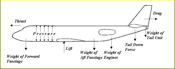
8. As mentioned earlier, the fuselage forms a structural link between the wings and the tail unit. It has to keep everything in the correct position and angles, and be capable of resisting the loads that they all impose upon it.
9. These include;

So all these forces are acting at the same time – another difficult structural problem for the aircraft designer.
10. In order to cope with these loads and forces, the fuselage is designed in three distinct parts
11. The three sections will carry the different loads in accordance with the task the aircraft is required to do, but in all types the centre section needs to be large and strong. This is necessary, as In flight, the whole aircraft will be supported by lift from the wings, transmitted through the centre of the fuselage to carry the other parts of the airframe.
12. From looking around at the aircraft on display at airshows, it is obvious that aircraft fuselage design varies.
13. Combat aircraft fuselages have many complex shapes and sizes due to the special tasks that they have to accomplish, whilst transport aircraft on the whole have a fairly standard tubular fuselage design.
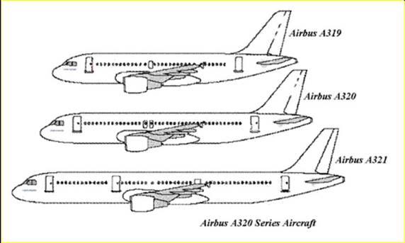
14. The reason for this is fairly straightforward, as the tubular section is a convenient shape for carrying bulk cargo or passengers and makes it possible to stretch fuselage designs to accommodate more cargo and/ or passengers. Stretching is achieved by inserting extra sections, pieces or plugs without resulting to a major re-design..
The result is mainly cylindrical designs with tapered nose and tail sections. An example of the stretch concept is the Airbus A320 family. The A319 is a shortened version of the A320 (so it has had sections removed), whilst the A321 has had sections added to make it longer.

15. There are some commercial aircraft that do not follow the circular corss section design standard. The Airbus A380 and Boeing 747 ‘Jumbo Jet’ have a fuselage cross-section that is oval in shape. This is to accommodate the double deck passenger section.
16. A similar method of construction to that used in the wings can be used for fuselages and tail units (or foreplanes)
In general, there are two methods of fuselage construction;
17. The welded steel truss was used extensively in aircraft designs in the interwar years and although superseded by monocoque designs, the welded steel truss is still used in some light aircraft and helicopters.
18. In a Welded Steel Truss, the structural elements resemble those of a bridge, with emphasis on using linked trianglular elements. The aerodynamic shape is completed by additional elements called Frames and Stringers and is then covered with fabric, metal sheeting or composite. The truss ensures a robust, uniform load bearing structure.
19. The monocoque design relies on the strength of the stressed skin within the airframe structure to share the loads, allowing for a much-reduced internal structure.
20. The monocoque design can be further sub-divided into three classes;
21. A Semi-Monocoque fuselage is constructed primarily of Aluminium Alloy.
The primary loads are taken by the Longerons, which usually extend across several points of support, holding the bulkheads, frames and formers. These are supplemented by Stringers, which are more numerous and lighter in weight than longerons and have some rigidity, but are chiefly used for giving shape and allow attachment of the skin.
By using stringers and longerons the designer can prevent tension and compression stresses from bending the fuselage. The bulkheads and formers hold the stringers in place and all these structural elements join together to provide a rigid fuselage framework.
The stressed skin is then attached to the longerons, bulkheads and the other structural members, such as the frames, which protrude into the fuselage interior by about 100 - 150 mm, leaving the rest of the fuselage clear for payload.
Ultimately, it is the stressed skin that carries part of the structural load of the airframe. Although, the designer will try to find the best compromise of skin strength (and weight) and frame and stringer strength, it should be noted that the skin thickness will vary with the load being carried and the stresses sustained at any given location as a result. A general design rule is that the skin will end up taking approximately half of the loads.
22. There are a number of advantages to utilising a semi-monocoque fuselage in an airframe design.
23. It leaves a large proportion of the inside free to accommodate crew, passengers and cargo as the loads that would have normally been carried by a Welded Steel Truss in previous designs are carried largely by the stressed skin.
24. The Bulkhead, Frames, Stringers and Longerons aid in producing a streamlined fuselage and add to the strength and rigidity of the structure.
25. As a semi-monocoque design relies on a number of structural members for strength and rigidity, the fuselage can withstand a reasonable amount of damage.
26. Loads from pressurisation can be up to 5600 kilogrammes force per square metre (that is a force equal to the weight of six cars for every square metre of fuselage skin). This is easier to contain in semi-monocoque construction.
27. So we have established that using a circular or oval cross section allows the fuselage to be pressurised, but how do we ensure that the ends of the tube are sealed? The answer lies in the shell of an egg!
28. The nose and tail of the fuselage uses double curvature bulkheads, like the surface of an egg, to make the skin even stiffer. Pressure bulkheads are fitted in the nose and close to the tail of most aircraft. They are flat discs, like a drum skin, or curved, like a breakfast bowl (see figure below). Their job is to withstand the loads imposed by pressurisation of the fuselage.

29. Unlike a combat aircraft, in a civil airliner, the cabin will require a floor. This consists of beams across the inside of the fuselage and covered in sheet alloy or composite panels.
30. This ensures a flat surface for walking on and fitting seat and it also allows the designer to compartmentalise (or divide up) the fuselage
This leaves space for luggage and the many aircraft systems in the lower fuselage space.
31. To allow for doors and windows, the fuselage must also include cut-outs, but this causes the engineers structural problems as the fuselage needs to be strengthened around them in order that the structural integrity of the airframe is not impaired
Therefore, it is vitally important to make sure that any loads can be routed around the cut-outs, and spread evenly into surrounding skin and structure.
32. The ideal shape for a cut-out in a fuselage is an ellipse, and many aircraft have windows this shape. Although widely known now, in the early days of semi-monocoque pressurised airframe design the implications of cut-outs and fatigue were less well defined and it took the De Havilland Comet disasters to fully realise this.
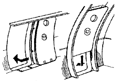
33. However, elliptical shapes are not very practical for cabin doors, and the more usual shape is a rectangular with rounded corners.
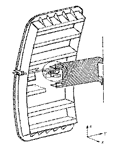
34. The 2 examples below are opened inwards, and so form a ‘plug’ when closed.

However, most modern commercial aircraft have outward opening cabin doors, so as to maximise the amount of internal space available. An example of a modern cabin door is given below.

35. Airframes must also include other access doors for maintenance and allow stowage of those components not required for flight, such as the undercarriage. In particular the cargo compartment needs a door, and some aircraft designed for transporting cargo have larger doors. Like cabin doors, these still need to resist the cabin pressure and maintain the strength of the fuselage, but are often a simpler hinge arrangement with a robust locking mechanism.
36. At the beginning of this chapter, we said that combat aircraft fuselages can be quite different from other aircraft. For example, the pressurised space is usually smaller, containing just the cockpit and perhaps an electronics bay, and pressures are much lower, because the pilot also uses an oxygen mask.
Additionally, the fuselage will probably have a strong beam, called the ‘keel beam’, which runs fore and aft, and many of the major parts, like the engines, cannon and undercarriage are mounted to it.
37. Far from the fuselage being a simple structural component of the airframe, it is itself a complex assembly. The fuselage has to be able to cope with not only those loads exerted on it during flight, but it also must cope with being pressurised.
38. It also needs to be spacious, in order to accommodate passengers and cargo, but yet structurally strong and rigid to withstand the loads.
39. You should now have an understanding of both the function of the fuselage, the methods of construction and the specific considerations that need to be addressed during its design.
Source: https://www.2473atc.org.uk/trainingMaterial/Master/MASTER%20airframes/Chapter%204%20Fuselage.doc
Web site to visit: https://www.2473atc.org.uk
Author of the text: indicated on the source document of the above text
If you are the author of the text above and you not agree to share your knowledge for teaching, research, scholarship (for fair use as indicated in the United States copyrigh low) please send us an e-mail and we will remove your text quickly. Fair use is a limitation and exception to the exclusive right granted by copyright law to the author of a creative work. In United States copyright law, fair use is a doctrine that permits limited use of copyrighted material without acquiring permission from the rights holders. Examples of fair use include commentary, search engines, criticism, news reporting, research, teaching, library archiving and scholarship. It provides for the legal, unlicensed citation or incorporation of copyrighted material in another author's work under a four-factor balancing test. (source: http://en.wikipedia.org/wiki/Fair_use)
The information of medicine and health contained in the site are of a general nature and purpose which is purely informative and for this reason may not replace in any case, the council of a doctor or a qualified entity legally to the profession.
The texts are the property of their respective authors and we thank them for giving us the opportunity to share for free to students, teachers and users of the Web their texts will used only for illustrative educational and scientific purposes only.
All the information in our site are given for nonprofit educational purposes