Friction is the resistance to motion which takes place when one body is moved upon another, and is generally defined as "that force which acts between two bodies at their surface of contact, so as to resist their sliding on each other." The force of friction, F, bears according to the conditions under which sliding occurs - a certain relation to the pressure between the two bodies; this pressure is called the normal pressure N. The relation between force of friction and normal pressure is given by the coefficient of friction, generally denoted by the Greek letter.
If a body is placed on an inclined plane, the friction between the body and the plane will prevent it from sliding down the inclined surface, provided the angle of the plane with the horizontal is not too great.
There will be a certain angle, however, at which the body will just barely be able to remain stationary, the frictional resistance being very nearly overcome by the tendency of the body to slide down. This angle is termed the angle of repose, and the tangent of this angle equals the coefficient of friction. The angle of repose is frequently denoted by the Greek letter. Thus π = tan q.

Figure 1 – Effect of Lubricant on Friction
A greater force is required to start a body from a state of rest than to merely keep it in motion, because the friction of rest is greater than the friction of motion.
A lubricant is used for one or more of the following purposes:
The range of materials used as lubricants has been greatly broadened over the years so that in addition to oils and greases many plastics and solids and even gases are now being applied in this role. The only limitations on many of these materials are their ability to replenish themselves, to dissipate frictional heat, their reaction to high environmental temperatures, and their stability in combined environments. Because of the wide selection of lubricating materials available, great care is advisable in choosing the material and the method of application. The following types of lubricants are available:
Tap wrenches are tools used to hold and turn a tap when producing internal threads by hand. They are made from steel and usually have:
Hand taps are made from carbon or high speed steel that is hardened and tempered and have:

Figure 2 - Hand Tap
Bar-type tap wrenches have a flat centre section holding jaws shaped to grip the squared end of the tap. One sliding jaw is adjusted by a screw operated by rotating one of the handles about its axis. The ends of the two handles are knurled.
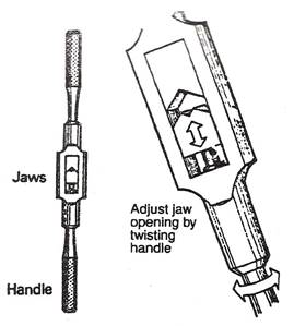
Figure 3 - Bar Type Tap Wrench
Tee-type tap wrenches have a small adjustable two-jaw chuck on the end of a stem with a handle. The largest capacity takes taps up to 13 mm in size. One hand is used to turn the handle.
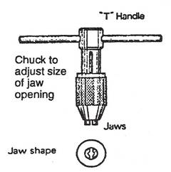
Figure 4 - "T"-Type Tap Wrench
Pin chucks for delicate tapping of small threads in instruments. Pin chucks have a very small adjustable two-jaw chuck mounted on the end of a knurled rod.
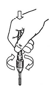 Figure 5 - Pin Chunk for Instrument Threads
Taps are normally used in sets of three, to allow progressive cutting of the threads.
Regular hand taps are used for most general work. Each set consists of a taper, intermediate and plug or buttoning taps. Each tap in a set has identical length and thread measurements and only the tapered lead is different.
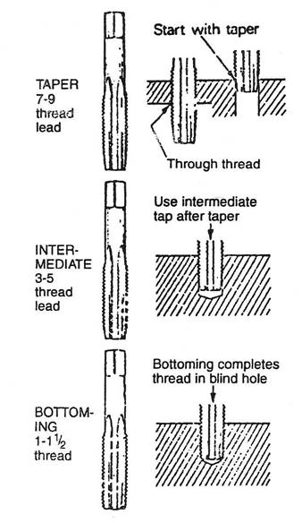
Holes of the correct size and condition are essential for successful tapping. The importance of drilling tapping holes correctly is shown in Figure 6.
For deep hole tapping or average commercial work a thread depth of 60% - 70% will usually provide a greater strength than that of the mating screw.

Figure 6 - Holes for Tapping
For correct drilling:
Nom. Dia. Tap m/m |
Pitch m/m |
Tapping Drill |
Nom. Dia. Tap m/m |
Pitch m/m |
Tapping Drill |
2.0 |
0.40 |
1.65 or 1.60 m/m |
14.0 |
1.50 |
12.50 or 12.60 m/m |
2.2 |
0.45 |
1.80 or 1.75 m/m |
14.2 |
1.25 |
12.80 or 12.90 m/m |
2.5 |
0.45 |
2.10 or 2.05 m/m |
16.0 |
2.00 |
14.00 m/m |
3.0 |
0.50 |
2.55 or 2.50 m/m |
16.0 |
1.50 |
14.50 or 14.60 m/m |
3.5 |
0.60 |
2.95 or 2.90 m/m |
18.0 |
2.50 |
15.50 or 39/64" |
4.0 |
0.70 |
3.30 m/m |
18.0 |
1.50 |
16.50 m/m |
5.0 |
0.80 |
4.20 m/m |
20.0 |
2.50 |
17.50 or 11/16" |
5.0 |
0.50 |
4.50 m/m |
20.0 |
1.50 |
18.50 m/m |
6.0 |
1.00 |
5.10 or 5.00 m/m |
22.0 |
2.50 |
19.50 or 19.75 m/m |
6.0 |
0.75 |
5.20 or 5.30 m/m |
24.0 |
3.00 |
21.00 or 21.25 m/m |
7.0 |
1.00 |
6.10 or 6.00 m/m |
27.0 |
3.00 |
24.00 or 24.25 m/m |
8.0 |
1.25 |
6.90 or 6.80 m/m |
30.0 |
3.50 |
26.50 or 1.3/64" |
8.0 |
1.00 |
7.00 or 7.10 m/m |
33.0 |
3.50 |
29.50 or 1.5/32" |
9.0 |
1.25 |
7.90 or 7.80 m/m |
36.0 |
4.00 |
32.00 or 1.1/4" |
10.0 |
1.50 |
8.60 or 8.50 m/m |
39.0 |
4.00 |
35.00 or 1.3/8" |
10.0 |
1.25 |
8.80 or 8.90 m/m |
42.0 |
4.50 |
1.31/64" or 37.50 m/m |
10.0 |
1.00 |
9.00 or 9.10 m/m |
45.0 |
4.50 |
1.39/64" or 40.50 m/m |
11.0 |
1.50 |
9.60 or 9.50 m/m |
48.0 |
5.00 |
1.45/64" or 43.00 m/m |
12.0 |
1.75 |
10.40 or 10.20 m/m |
52.0 |
5.00 |
1.55/64" or 47.00 m/m |
12.0 |
1.50 |
10.50 or 10.60 m/m |
56.0 |
5.50 |
2" or 50.50 m/m |
14.0 |
2.00 |
12.20 or 12.00 m/m |
60.0 |
5.50 |
2.5/32" |
Table 1 - Tapping Drill Sizes for ISO Metric Threads
The formulae below are used for calculating the depth of threads:
P = pitch
ISO = 0.6495 x P
BSW = 0.640 x P
BA = 0.600 x P
Nominal Dia. Tap |
B.S.W. |
B.S.F. |
N.C. |
N.F. |
1/16" |
1.15 m/m |
- |
- |
- |
3/32" |
1.9 m/m |
- |
- |
- |
1/8" |
2.55 m/m |
- |
- |
- |
5/32" |
3.1 m/m |
- |
- |
- |
3/16" |
3.7 m/m |
5/32" |
- |
- |
7/32" |
11/64" |
4.6 m/m |
- |
- |
1/4" |
5.1 m/m |
5.3 m/m |
5.2 m/m |
5.5 m/m |
5/16" |
6.5 m/m |
6.8 m/m |
6.6 m/m |
6.9 m/m |
3/8" |
5/16" |
8.3 m/m |
8 m/m |
8.5 m/m |
7/16" |
9.3 m/m |
9.7 m/m |
9.4 m/m |
9.9 m/m |
1/2" |
10.5 m/m |
7/16" |
10.8 m/m |
11.5 m/m |
9/16" |
12.1 m/m |
1/2" |
12.2 m/m |
12.9 m/m |
5/8" |
13.5 m/m |
14 m/m |
13.5 m/m |
14.5 m/m |
11/16" |
15.0 m/m |
15.5 m/m |
5/8" |
19.32" |
3/4" |
41/64" |
16.75 m/m |
16.5 m/m |
11/16" |
7/8" |
19.25 m/m |
25/32" |
49/64" |
20.5 m/m |
1" |
22 m/m |
22.75 m/m |
22.25 m/m |
23.25 m/m |
1.1/8" |
24.75 m/m |
25.5 m/m |
63/64" |
26.5 m/m |
1.1/4" |
1.3/32" |
1.1/8" |
1.7/64" |
29.5 m/m |
1.3/8" |
1.3/16" |
31.5 m/m |
30.75 m/m |
1.19/64" |
1.1/2" |
33.5 m/m |
1.23/64" |
1.21/64" |
36.00 m/m |
1.5/8" |
35.5 m/m |
1.31/64" |
36 m/m |
- |
1.3/4" |
39.0 m/m |
1.19/32" |
1.35/64" |
- |
1.7/8" |
1.5/8" |
1.23/32" |
- |
- |
2" |
44.5 m/m |
1.27/32" |
1.25/32" |
- |
Table 2 - Tapping Drills for Fractional Inch size Taps
No. |
B.A. |
N.C. |
N.F. |
0 |
5.10 m/m |
- |
1.25 m/m |
1 |
4.50 m/m |
1.55 m/m |
1.55 m/m |
2 |
4.00 m/m |
1.85 m/m |
1.90 m/m |
3 |
3.40 m/m |
2.10 m/m |
2.15 m/m |
4 |
3.00 m/m |
2.35 m/m |
2.40 m/m |
5 |
2.65 m/m |
2.65 m/m |
2.70 m/m |
6 |
2.30 m/m |
2.85 m/m |
2.95 m/m |
7 |
2.05 m/m |
- |
- |
8 |
1.80 m/m |
3.50 m/m |
9/64" |
9 |
1.55 m/m |
- |
- |
10 |
1.40 m/m |
3.90 m/m |
4.10 m/m |
11 |
1.20 m/m |
- |
- |
12 |
1.05 m/m |
4.50 m/m |
4.70 m/m |
Table 3 - Tapping Drills for Taps with a Designating Number
B.A. - British Association
N.C. - National Coarse
U.N.C. - Unified Coarse
N.F. - National Fine
U.N.F. - Unified Fine
The method of tapping a through hole is shown in the following sequence:

Figure 7 - Tapping a Through Hole
Blind holes cannot be tapped right to the bottom. As the tapping hole is drilled, depth gauge on the drilling machine should be used. The depth of the hole should be greater than the depth of thread required.
A nut on the top to act as a stop can be used.
Use normal tapping procedures but clear out chips frequently.
Clear chips from the job by inverting small jobs.
Never blow out chips with compressed air.
If excessive resistance is felt before the measured depth is reached, clear out all the chips and try again with the taper tap. Repeat the procedure of changing taps until the correct depth is reached.

Figure 8 - Tapping a Blind Hole
The stock is the tool used to hold and turn a threading die when producing external threads by hand.
Stocks are made from mild steel or malleable cast iron and usually have:
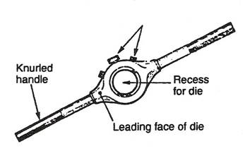
Figure 9 – Stock
Dies are made from alloy tool steel that is hardened and tempered and have:

Figure 10 - Large Button Die
The size and type of threads is marked on the die.
The cutting size marked on the die corresponds to the maximum diameter of the material to be threaded. Use on oversize material will damage the die.
Round sections and pipes are prepared for threading by filing, cutting or grinding a small chamfer on the end. To start a thread, insert the die with its leading end and face on the leading side of the stock.

Figure 11 - Starting a Thread
Button-type stocks are solid stocks with a shoulder and locking screws. They hold a single piece disc-shaped diameter.

Figure 12 - Button Pattern Stock with Button Die
Quick cut stocks are designed to hold two-piece adjustable dies.
These dies usually have a double level on their outer sides to match the stock. The dies may be held in the cap or collet into which a guide is screwed. Adjusting screws in the cap bear on the back of the die halves. Greater adjustment of the depth of thread is possible with two piece dies.

Figure 13 - Assembling a Two-Piece Die

Figure 14 - ????
Elastic-type stocks have one side split and fitted with a clamping screw.
Pins in the recess of the stock locate a guide plate.
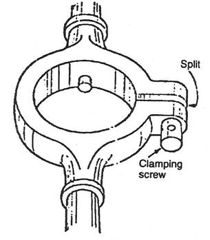
Figure 15 - Elastic Type Stock
After grinding the chamfer on the edge of the material; the sequence for cutting the thread is shown in the following diagram.

Figure 16 - Cutting a Thread
If the thread has to be run right to the shoulder:
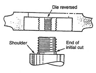
Figure 17 - Cutting a Thread to a Shoulder
Source: http://local.ecollege.ie/Content/APPRENTICE/liu/sheetmetal_notes/Tapping,%20Threading%20and%20Assembly_M1_U7.doc
Web site to visit: http://local.ecollege.ie/
Author of the text: indicated on the source document of the above text
If you are the author of the text above and you not agree to share your knowledge for teaching, research, scholarship (for fair use as indicated in the United States copyrigh low) please send us an e-mail and we will remove your text quickly. Fair use is a limitation and exception to the exclusive right granted by copyright law to the author of a creative work. In United States copyright law, fair use is a doctrine that permits limited use of copyrighted material without acquiring permission from the rights holders. Examples of fair use include commentary, search engines, criticism, news reporting, research, teaching, library archiving and scholarship. It provides for the legal, unlicensed citation or incorporation of copyrighted material in another author's work under a four-factor balancing test. (source: http://en.wikipedia.org/wiki/Fair_use)
The information of medicine and health contained in the site are of a general nature and purpose which is purely informative and for this reason may not replace in any case, the council of a doctor or a qualified entity legally to the profession.
The texts are the property of their respective authors and we thank them for giving us the opportunity to share for free to students, teachers and users of the Web their texts will used only for illustrative educational and scientific purposes only.
All the information in our site are given for nonprofit educational purposes